Facebook Pixel

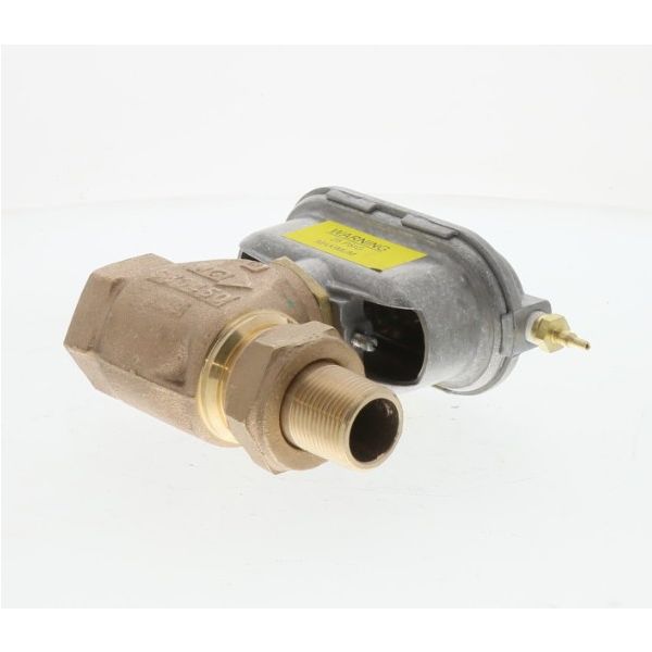
Johnson Controls VG7251LS+3801D Normal Open Globe Valve 4-8 PSI 3/4" Union Brass 7.3Cv

Special Price $376.42 Regular Price $417.83
In stock
SKU
VG7251LS+3801D
The Johnson Controls VG7251LS+3801D Union Globe With Auxiliary Actuator is a valve designed for use in the HVAC system, more specifically for regulating the flow of water or steam. This valve has a fitting of size 3/4" and has a high CV of 7.3 and hence can be used in applications where moderate to high flow rates are needed. Designed to work at a pressure ranging from 4 PSI to 8 PSI, the valve maintains efficiency regardless of the system’s load. The incorporated auxiliary actuator provides additional versatility with the ability to control the actuator remotely or automatically, which is particularly essential for managing temperature and pressure in heating or cooling systems.
https://www.partshnc.com/media/catalog/product/v/g/vg7251ls-3801d.jpg

Specifications

  • Weight:3.12 Lbs
  • Size: 3/4"
  • Flow Coefficient (Cv): 7.3
  • Pressure Range: 4 PSI to 8 PSI
  • Type: Union Globe

PRODUCT OVERVIEW:
As a part of the hydronic flow control system, the Johnson Controls VG7251LS+3801D Normal Open Globe Valve controls fluid circulation in hot water, chilled water, and steam HVAC systems. This unit combines a 3/4" union brass globe valve body rated for a 7.3Cv flow capacity with a pneumatic actuator calibrated for a 4 to 8 PSI operating pressure range. The actuator responds to pneumatic control signals to adjust the valve position and regulate fluid passage through the connected piping circuit.

PNEUMATIC ACTUATION MECHANICS:
Pneumatic control begins the valve-positioning process by acting on the actuator diaphragm and associated spring mechanism. The diaphragm converts the applied air pressure into linear movement of the valve stem, while the spring provides the opposing force needed for position control. With the normally open arrangement, the stem remains retracted when the actuator is not pressurized. Increasing control pressure moves the stem toward the seat and progressively restricts fluid passage.

HYDRONIC SYSTEM FLOW MODULATION:
Within a hydronic circuit, the globe valve regulates fluid movement by changing the available passage through the valve body. As the valve stem shifts, the opening between the valve seat and internal plug changes to increase or restrict circulation through the connected piping. This modulation allows the HVAC control system to adjust fluid flow according to the operating demand of the hydronic circuit.

REPLACEMENT GUIDELINES:
Replacement may be appropriate when the valve fails to regulate fluid passage, the actuator does not respond correctly to the control signal, or physical deterioration affects valve movement or sealing. For the Johnson Controls VG7251LS+3801D, replacement should be based on matching the existing valve and actuator identification with the HVAC equipment requirements, piping arrangement, control method, and applicable manufacturer documentation.

Common Failure Symptoms:

  • Inability to reduce or shut off fluid flow when pneumatic control air pressure increases.
  • Fluid leakage around the valve stem or union connection joints.
  • Failure of the valve stem to return to the fully open position when pneumatic pressure is vented.
  • External air leaks from the pneumatic actuator housing.

EQUIPMENT COMPATIBILITY:
The Johnson Controls VG7251LS+3801D applies to hot water, chilled water, and steam HVAC systems designed for normally open pneumatic globe valves. Before purchasing, verify that the replacement part matches the exact attributes listed in the Technical Specifications table, including the brand, part number, product type, equipment model, valve configuration, actuator pressure range, body size, body material, connection type, flow coefficient and applicable manufacturer documentation.

Technical Specifications:
Product identification:
Brand: Johnson Controls
Part Number: VG7251LS+3801D
Product Type: Globe Valve Assembly
Physical specifications:
Valve Size: 3/4"
Connection Type: Union
Material details:
Body Material: Brass
Operating conditions:
Actuator Pressure Range: 4-8 PSI
Flow & capacity specifications:
Flow Coefficient (Cv): 7.3 Cv

Write Your Own Review
You're reviewing:Johnson Controls VG7251LS+3801D Normal Open Globe Valve 4-8 PSI 3/4" Union Brass 7.3Cv
Your Rating
Customer Questions
What maintenance is required for the Johnson Controls VG7251LS+3801D Globe Valve?

Inspect the valve regularly for leaks and ensure smooth actuator movement. Clean internal components to prevent debris buildup that may restrict flow. Tighten fittings and check seals periodically. Routine servicing prevent accurate temperature and pressure control.

What are common issues with the Johnson Controls VG7251LS+3801D Globe Valve?

  • Internal leakage due to worn seals or seat damage.
  • Sticking or sluggish valve movement from debris buildup.
  • Pressure regulation instability affecting flow control.
  • Actuator malfunction causing incomplete valve opening or closing.

What does normally open mean for the Johnson Controls VG7251LS+3801D globe valve?

Normally open means the valve remains in its open flow position when the actuator is not applying the closing force.

How does the Johnson Controls VG7251LS+3801D regulate hydronic flow?

The valve regulates hydronic flow by changing the available passage through the globe valve as the stem moves.

How does the pneumatic actuator control the globe valve?

The pneumatic actuator converts changes in control pressure into stem movement that adjusts the valve opening within the hydronic circuit.

What type of HVAC systems use the Johnson Controls VG7251LS+3801D?

The Johnson Controls VG7251LS+3801D is used in compatible HVAC systems that require controlled flow of hot water, chilled water, glycol solutions, or steam.

What happens when the actuator changes the valve position?

Changing the valve position alters the available flow passage, allowing the HVAC control system to increase or restrict fluid movement through the connected piping.

Installation Steps

Step 1: Turn off system power and isolate the water/steam line; relieve pressure fully.

Step 2: Drain the section of piping where the valve will be installed.

Step 3: Remove the old valve and clean pipe threads or union connections.

Step 4: Install the new valve in the correct flow direction.

Step 5: Tighten union fittings securely and connect tubing.

Step 6: Restore system pressure and power, then test for leaks and proper modulation.