Facebook Pixel

Peco Controls TF115-001 SPDT Coiled Thermostat NEMA-4X Bulb 40°-110°F

Special Price $61.32 Regular Price $70.52
In stock
SKU
TF115-001
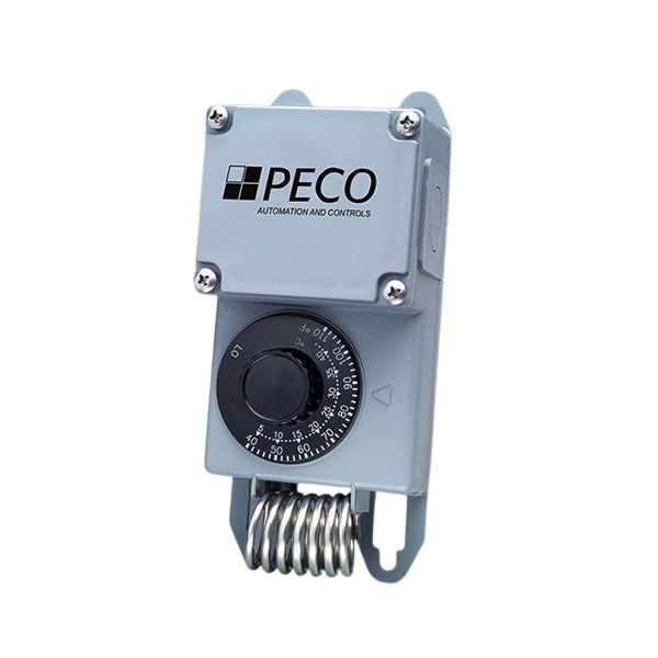
Peco Controls TF115-001 Thermostat is a part that can be used in different HVAC systems. This is an SPDT switch-type thermostat and is housed in a NEMA-4X enclosure which is suitable for a tough environment. The bulb sensor measures temperature fluctuations from 40°F up to 110°F. The coiled bulb responds to temperature variations by altering its dimensions which controls the heating or cooling system through the switch mechanism. The mechanical operation allows the thermostat to maintain a specific temperature range throughout a specified space.
https://www.partshnc.com/media/catalog/product/t/f/tf115-001_1.jpg

Specifications

  • Type: Thermostat
  • Switch Type: SPDT
  • Enclosure: NEMA-4X
  • Temperature Range: 40°F-110°F
  • Sensor Type: Bulb
Manufacturer Name: Peco Controls
Product Number: TF115-001
OEM Part Number: TF115-001
Product Description: 40/110F Nema4x Spdt Coiledbulb
Weight:0.71lbs/322.05g

Choose the best HVAC equipment parts and supplies from PartsHnC!

  • Same Day Shipping

  • Best Quality And Best Price

  • Wide Range of Inventory

  • Best Customer Service

Have More Questions or Need Help to Place The Order?
Reach us at (866)773-0907 or [email protected]

Write Your Own Review
You're reviewing:Peco Controls TF115-001 SPDT Coiled Thermostat NEMA-4X Bulb 40°-110°F
Your Rating
Customer Questions
What maintenance is required for the Peco Controls TF115-001 Thermostat?

Periodically check the thermostat for dust buildup that may affect temperature sensing accuracy. Clean the exterior with a dry, soft cloth and ensure vents are unobstructed. Verify wiring connections are secure and inspect for wear. Always switch off power before handling to prevent electrical hazards.

What are common issues with the Peco Controls TF115-001 Thermostat?

  • Inconsistent temperature readings or calibration drift.
  • Unresponsive controls or delayed system activation.
  • Wiring faults causing intermittent operation.
  • Display or control malfunctions affecting usability.

Installation Steps

Step 1: Disconnect power to HVAC system to prevent shock.

Step 2: Mount thermostat on suitable surface avoiding heat sources and airflow interference.

Step 3: Insert sensing coil in designated area for accurate temperature reading.

Step 4: Connect wiring terminals according to wiring diagram ensuring secure connections.

Step 5: Tighten mounting hardware and verify probe placement.

Step 6: Restore power and test switching operation and calibration.

Step 7: Confirm thermostat response across temperature range for proper switching.