Facebook Pixel

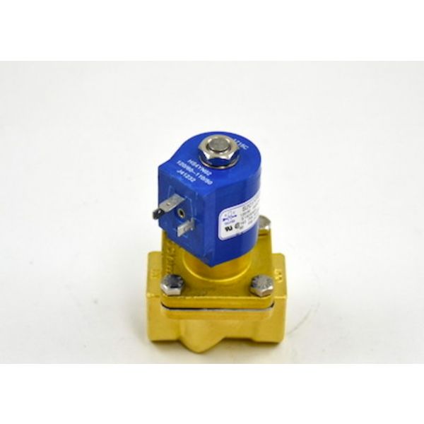
GC Valves S201YF02N5EG5E 3/4" Solenoid Valve N/C 0-200-PSI 120V

Special Price $344.77 Regular Price $382.69
Out of stock
SKU
S201YF02N5EG5E
The GC Valves S201YF02N5EG5E Solenoid Valve operates as a high-performance normally closed valve for both air and water applications. Operating at 3/4" with 0-200 pressure range and 120V input the valve controls flow via a DIN coil effectively. This valve delivers precise flow control for air and water lines while serving HVAC systems water treatment facilities and industrial applications. The valve features a robust structure that provides reliable solutions with leak prevention and decreased maintenance expenses. The simple installation process together with reliable operation enables the valve to improve system efficiency and prolong the operating longevity of heating ventilating and air conditioning equipment as well as industrial equipment.
https://www.partshnc.com/media/catalog/product/s/2/s201yf02n5eg5e.jpg

Specifications

  • Type: Solenoid Valve
  • Application: Air,Water
  • Coil: Din Coil
  • Size: 3/4"
  • Pressure Range: 0-200 PSI
  • Configuration: Normally Closed
  • Voltage: 120V

PRODUCT OVERVIEW:
Operating as an automated fluid control component within commercial and industrial piping circuits, the GC Valves S201YF02N5EG5E N/C Solenoid Valve manages internal media flow across equipment lines. This inline flow regulation unit features a 3/4" port configuration, a normally closed (N/C) operational state, and a 120V electrical rating for operating pressures spanning from 0 to 200 PSI. Serving as an automatic shutoff point, the unit maintains a secure seal at rest and opens upon electrical activation.

ELECTROMAGNETIC SWITCHING RESPONSE:
Within the actuator, an energized solenoid generates the magnetic force needed to shift its internal operator. The operator responds directly to changes in the electrical state established by the control circuit, moving through its designated operating path. This electromagnetic response provides the mechanical input required to change the valve's state. Once the electrical command ends, the magnetic force subsides, and the operator returns toward its inactive position.

CLOSED-STATE FLOW ISOLATION:
A normally closed configuration maintains separation within the valve's fluid pathway while the valve remains inactive. The internal closure stays positioned at its designated stopping point, preventing passage through the valve. This closed condition is maintained until the valve receives the command required for operation. The arrangement therefore establishes a defined isolation state within the connected line without relying on continuous electrical activation.

REPLACEMENT GUIDELINES:
Replacement may be appropriate when internal binding, seating deterioration, leakage, electrical failure, or physical damage prevents proper operation. For the GC Valves S201YF02N5EG5E, replacement may be necessary when the valve fails to respond to the operating command, does not maintain the required closed condition, or deterioration affects the housing or connections. Selection should be based on matching the existing valve identification with the equipment application, fluid service, piping arrangement, and control requirements.

Common Failure Symptoms:

  • Fluid flow is absent when the valve receives the required operating command.
  • Fluid continues to pass when the valve should remain closed.
  • Connected equipment does not receive the expected fluid flow during operation.
  • Fluid leakage develops around the valve body or connected ports.
  • Physical damage, cracking, corrosion, or deterioration is visible on the valve assembly.

EQUIPMENT COMPATIBILITY:
The GC Valves S201YF02N5EG5E N/C 3/4" Solenoid Valve 0-200-PSI 120V applies to specific fluid control and industrial processing systems produced by the manufacturer. Before purchasing, verify that the replacement part matches the exact attributes listed in the Technical Specifications table, including the brand, part number, product type, normal position, port size, operating voltage, and pressure rating.

Technical Specifications:
Product identification:
Brand: GC Valves
Part Number: S201YF02N5EG5E
Product Type: Solenoid Valve
Physical specifications:
Port Size: 3/4"
Operating conditions:
Pressure Rating: 0 - 200 PSI
Electrical specifications:
Voltage: 120V
Valve operation & control:
Normal Position: Normally Closed (N/C)

Write Your Own Review
You're reviewing:GC Valves S201YF02N5EG5E 3/4" Solenoid Valve N/C 0-200-PSI 120V
Your Rating
Customer Questions
What maintenance is required for the GC Valves S201YF02N5EG5E Solenoid Valve?

Inspect the solenoid valve regularly for debris buildup and ensure proper sealing of internal components. Clean the valve body and orifice periodically to maintain flow efficiency. This prevents sticking and ensures accurate operation under pressure.

What are common issues with the GC Valves S201YF02N5EG5E Solenoid Valve?

  • Coil failure from overheating or voltage instability.
  • Valve sticking due to dirt or internal debris buildup.
  • Leakage caused by worn seals or diaphragm damage.
  • Reduced performance from incorrect installation or pressure mismatch.

What does normally closed mean for the GC Valves S201YF02N5EG5E?

Normally closed means the valve maintains a closed flow pathway while it is in its inactive state and opens when the required operating command is provided.

How does the GC Valves S201YF02N5EG5E respond to an electrical command?

The solenoid responds to electrical input by generating the electromagnetic force needed to change the valve's operating state.

How does electromagnetic actuation change a solenoid valve's position?

Electromagnetic actuation produces magnetic force that moves the internal operator and shifts the valve mechanism between its operating states.

What role does flow isolation play in a normally closed valve?

Flow isolation prevents passage through the valve while the internal closure remains in its inactive position.

How does a solenoid valve interact with an automated control system?

The control system provides an electrical command that determines when the solenoid changes the valve's operating state within the equipment sequence.

Installation Steps

Step 1: Shut off power and fluid supply before installation.

Step 2: Verify coil compatibility and pressure rating.

Step 3: Install valve inline with flow arrow direction.

Step 4: Use tape on threaded connections and tighten securely.

Step 5: Wire coil per electrical diagram and ground properly.

Step 6: Restore pressure slowly and check for leaks and ensure safe operation.