Facebook Pixel

Belimo WAF Linkage AF/NF Actuators

Special Price $21.81 Regular Price $28.36
In stock
SKU
WAF
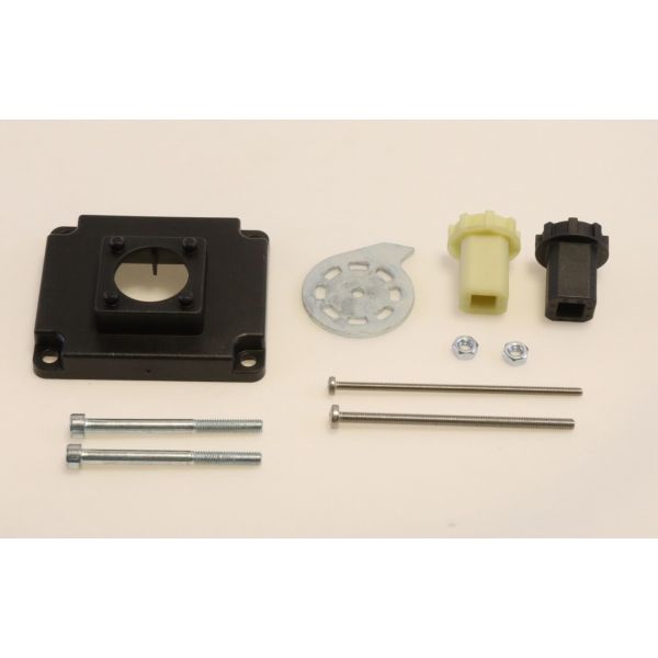
The Belimo WAF Linkage AF/NF Actuators provide an effective mechanical connection of dampers in commercial and residential control assemblies. It is implemented in the HVAC systems to regulate the damper movement and maintain the conditions unchanged to ensure that the actuators operate effectively. This element fits with actuator models and is used to give proper alignment and even distribution of torque. It is typically attached to air handling units, ventilation equipment, or duct assemblies and is an essential element of the execution of airflow and operation of the whole system.
Manufacturer:
https://www.partshnc.com/media/catalog/product/w/a/waf.jpg
Manufacturer Name: Belimo
Product Number: WAF
OEM Part Number: WAF
Product Description: Linkage Af/Nf Actuator/Valve
Weight:0.49lbs/222.26g

Choose the best HVAC equipment parts and supplies from PartsHnC!

  • Same Day Shipping

  • Best Quality And Best Price

  • Wide Range of Inventory

  • Best Customer Service

Have More Questions or Need Help to Place The Order?
Reach us at (866)773-0907 or [email protected]

Write Your Own Review
You're reviewing:Belimo WAF Linkage AF/NF Actuators
Your Rating
Customer Questions
What maintenance is required for the Belimo WAF Linkage Af/Nf Actuator/Valve?

Inspect the linkage periodically for a tight connection between the actuator and valve to ensure smooth motion. Check for damage, corrosion, or loosened mounting hardware. Verify proper actuator calibration and full travel operation during routine HVAC servicing. Keeping components aligned assists maintain accurate valve control.

What are common issues with the Belimo WAF Linkage Af/Nf Actuator/Valve?

  • Loose or misaligned linkage causing improper valve positioning.
  • Binding or sticking during operation.
  • Wear in coupling parts leading to lost motion.
  • Actuator not fully opening or closing the valve.
  • Mounting loosening from vibration or repeated cycling.

Installation Steps

Step 1: Disconnect system power and confirm no electrical supply to actuator circuit before starting.

Step 2: Isolate valve section and relieve line pressure if present.

Step 3: Mount linkage bracket onto valve stem, align correctly.

Step 4: Attach actuator to bracket ensuring secure fit.

Step 5: Connect wiring to actuator terminals per control diagram.

Step 6: Set stroke/position calibration and test smooth movement.

Step 7: Restore power and check operation.