Facebook Pixel

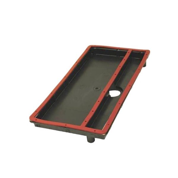
Amana-Goodman 2820007S Collector Box Assembly

Special Price $166.56 Regular Price $191.54
In stock
SKU
2820007S
The Amana-Goodman 2820007S Collector Box Assembly is a spring fitting appliance, that is utilized in HVAC systems in gas furnaces. It is used to capture and channel the fumes resulting from the furnace burner onto the venting system. This assembly also plays the role of preventing leakage and proper flow of the combustion byproducts to the outside environment. The collector box minimizes energy loss and improves the efficiency of the furnace through the optimization of gas exhaust. It has been designed for use with different Amana and Goodman models supported by long-lasting operational capacity.
https://www.partshnc.com/media/catalog/product/2/8/2820007s.jpg

Specifications

  • Type: Collector Box Assembly
    Manufacturer Name: Amana-Goodman
    Product Number: 2820007S
    OEM Part Number: 2820007S
    Product Description: Collector Box Assy
    Weight:3.2lbs/1451.49g

    Choose the best HVAC equipment parts and supplies from PartsHnC!

    • Same Day Shipping

    • Best Quality And Best Price

    • Wide Range of Inventory

    • Best Customer Service

    Have More Questions or Need Help to Place The Order?
    Reach us at (866)773-0907 or [email protected]

    Write Your Own Review
    You're reviewing:Amana-Goodman 2820007S Collector Box Assembly
    Your Rating
    Customer Questions
    What maintenance is required for the Amana-Goodman 2820007S Collector Box Assembly?

    Inspect collector box for cracks or corrosion during routine servicing. Clean debris and keep drain passages clear to prevent moisture buildup. Check seals for leaks and ensure secure mounting for safe operation.

    What are common issues with the Amana-Goodman 2820007S Collector Box Assembly?

    • Cracks or corrosion in housing.
    • Air leakage from worn seals.
    • Drain blockage causing moisture buildup.
    • Warping from high heat exposure.
    • Loose mounting causing vibration/noise.
    • Restricted airflow through collector chamber.

    Installation Steps

    Step 1: Isolate electrical supply and allow unit to cool fully before access.

    Step 2: Remove inducer assembly and detach existing collector box connections and tubing.

    Step 3: Clean heat exchanger interface area to ensure proper sealing surface.

    Step 4: Position new collector box assembly and align all ports with outlet and drain points.

    Step 5: Tighten mounting hardware evenly and reconnect vent and drain lines securely.

    Step 6: Restore power and run system check, confirming stable operation and no leakage.