Facebook Pixel

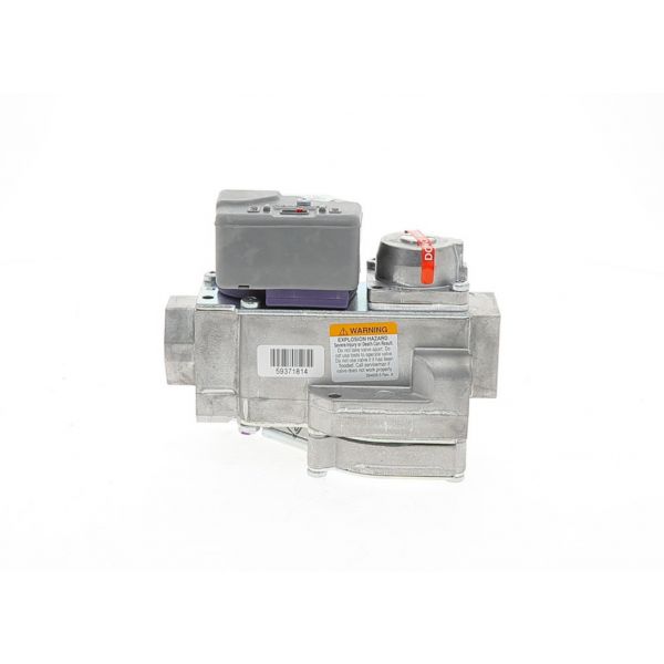
Amana-Goodman 0151M00024S Natual Gas Valve 3.5" WC 24V

Special Price $259.19 Regular Price $287.70
In stock
SKU
0151M00024S
The Amana-Goodman 0151M00024S Natural gas valve is a 3.5 inch WC 24V for residential and light commercial heat systems. They are used to control the flow of natural gas to the burner in your furnace or boiler which is vital in the home. It uses a 24 volt electrical signal and has a small and robust structure. The gas valve uses a solenoid for controlling the opening and closing of the gas path. When the thermostat wants heat, it opens the circuit to the gas valve which is 24 volts. This signal energizes the solenoid, which in turn opens the valve stem and lets natural gas to the burner.
Manufacturer:

https://www.partshnc.com/media/catalog/product/0/1/0151m00024s.jpg

Specifications

  • Type: Natual Gas Valve
  • Pressure Range: 3.5" Water Column
  • Voltage: 24V
Manufacturer Name: Amana-Goodman
Product Number: 0151M00024S
OEM Part Number: 0151M00024S
Product Description: 3.5"Wc 24V Nat Gas Valve
Weight:2.45lbs/1111.3g

Choose the best HVAC equipment parts and supplies from PartsHnC!

  • Same Day Shipping

  • Best Quality And Best Price

  • Wide Range of Inventory

  • Best Customer Service

Have More Questions or Need Help to Place The Order?
Reach us at (866)773-0907 or [email protected]

Write Your Own Review
You're reviewing:Amana-Goodman 0151M00024S Natual Gas Valve 3.5" WC 24V
Your Rating
Customer Questions
What maintenance is required for the Amana-Goodman 0151M00024S Natural Gas Valve?

Inspect the valve for gas leaks and ensure secure electrical connections regularly. Clean external surfaces and check wiring integrity to maintain reliable operation. Proper maintenance prevents gas flow issues and ensures better heating performance.

What are common issues with the Amana-Goodman 0151M00024S Natural Gas Valve?

  • Gas valve may fail to open or close due to internal solenoid malfunction.
  • Inconsistent gas flow causing weak or no burner ignition.
  • Electrical coil failure leading to no response from thermostat signal.
  • Gas leakage or pressure irregularities affecting heating performance.

Installation Steps

Step 1: Turn off power and gas supply and confirm zero voltage.

Step 2: Remove access panel to reach valve assembly.

Step 3: Label and disconnect wiring and gas connections carefully.

Step 4: Remove old valve and position new valve in same orientation.

Step 5: Secure fittings and reconnect wiring to matching terminals.

Step 6: Check for leaks after restoring gas and power using approved leak solution.