
Facebook Pixel

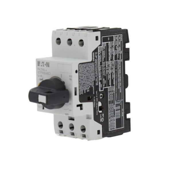
Cutler Hammer-Eaton XTPR004BC1 Xt Manual Motor Protector

Special Price $154.06 Regular Price $177.17
In stock
SKU
XTPR004BC1
The Cutler Hammer-Eaton XTPR004BC1 XT Manual Motor Protector is used to protect electric motors against short-circuit conditions and overload in HVAC systems. This combination of manual switching, thermal, and magnetic trip settings breaks the electrical circuit when current flow is beyond preset limits to avoid damaging the connected motor in the systems. The adjustable protection settings allow the parts to be changed to match the motor current requirements while still working well with the equipment upstream. It is connected to the motor power circuit by means, of terminal connections and is mounted in the electrical control panel.
https://www.partshnc.com/media/catalog/product/x/t/xtpr004bc1-cutler-hammer-eaton_partshnc.jpg
Manufacturer Name: Cutler Hammer-Eaton
Product Number: XTPR004BC1
OEM Part Number: XTPR004BC1
Product Description: Xt Manual Motor Protector
Weight:0.74lbs/335.66g

Choose the best HVAC equipment parts and supplies from PartsHnC!

  • Same Day Shipping

  • Best Quality And Best Price

  • Wide Range of Inventory

  • Best Customer Service

Have More Questions or Need Help to Place The Order?
Reach us at (866)773-0907 or [email protected]

Write Your Own Review
You're reviewing:Cutler Hammer-Eaton XTPR004BC1 Xt Manual Motor Protector
Your Rating
Customer Questions
What maintenance is required for the Cutler Hammer-Eaton XTPR004BC1 Motor Protector?

Inspect the motor protector regularly for loose terminals, damaged housing, and signs of overheating or electrical arcing. Test the switching and reset functions during scheduled equipment inspections to ensure proper operation. Keep the system free of dust and contaminants that could affect performance. Always disconnect power and follow electrical safety procedures before servicing or inspection.

What are common issues with the Cutler Hammer-Eaton XTPR004BC1 Motor Protector?

  • Failure to trip under overload conditions.
  • Reset mechanism not functioning properly.
  • Loose terminal connections causing intermittent operation.
  • Contact wear leading to unreliable switching.
  • Overheating or discoloration from excessive current loads.

Installation Steps

Step 1: Turn off all power and verify lockout/tagout before installation.

Step 2: Mount the protector on din rail or panel according to rating requirements.

Step 3: Connect line and load wiring to labeled terminals securely, ensure correct phase matching.

Step 4: Set current and protection dial to motor specifications as per nameplate.

Step 5: Tighten terminals and check alignment, ensure no loose connections.

Step 6: Restore power and test trip operation safely under no-load conditions.