Schneider Electric (Viconics) VT8650U5500B Indoor Air Quality Controller
Specifications
- Type: Indoor Air Quality Controller
Loyalty Program
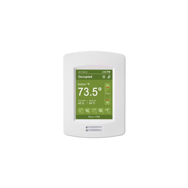
The Schneider Electric (Viconics) VT8650U5500B is a programmable and application-specific room controller with customizable screen colors. It's a versatile controller suitable for rooftops, heat pumps, and indoor air quality applications in commercial and high-end hospitality markets. The VT8650U5500B Schneider Electric progammable thermostat offers security features such as a PIR cover to prevent unauthorized access. With permanent program retention, settings remain intact even during power losses. Additional functionalities include mixed-air control outputs (0-10V), mixed-air sensor input for outdoor air quality consideration, and mixed-air setpoint economizer changeover for automatic switching to economizer mode in favorable outdoor conditions.
The thermostat allows customization with two or four configurable events per day, progressive recovery options, and a choice between 12-hour or 24-hour clock formats, maintaining time settings for up to six hours without power. The Occ/Unocc auxiliary contact out provides a signal for controlling other equipment based on occupancy, and BACnet MS/TP support facilitates communication with BACnet building automation systems. For wireless connectivity, an optional Zigbee Pro/Wireless communication module is available, enabling seamless communication with other compatible devices.
Key features:
Physical Issues:
System and Functionality Issues:
Same Day Shipping
Best Quality And Best Price
Wide Range of Inventory
Best Customer Service
What are the benefits of using the Schneider Electric progammable thermostat?
My VT8650U5500B is not working properly. What should I do?
Step 1: Turn off HVAC system power and follow lockout/tagout safety procedures before handling wiring.
Step 2: Remove the existing old wall-mounted controller and label all low-voltage control wires.
Step 3: Mount the backplate securely on a level surface away from direct to install new airflow or heat sources.
Step 4: Connect wiring to terminals per wiring diagram.
Step 5: Attach controller faceplate and restore power.
Step 6: Configure settings via touchscreen and check communication with HVAC system and sensors.