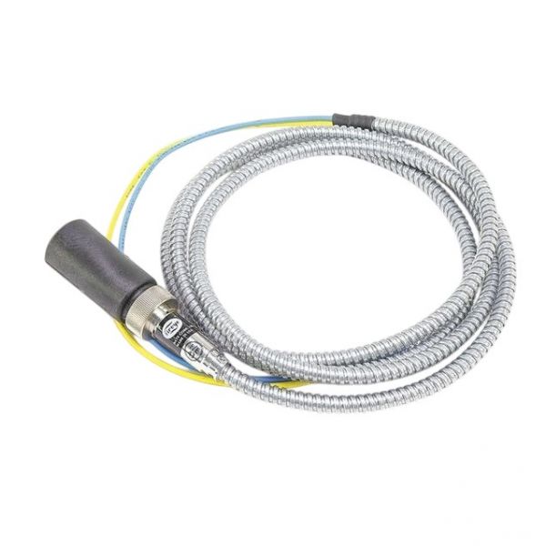
Fireye UV7A4 UV Scanner 1/2" NPT 4' Conduit
Special Price $248.57 Regular Price $275.91
In stock
SKU
UV7A4

The Fireye UV7A4 Ultra-Violet Scanner operates boilers furnaces and industrial burners safely by identifying UV radiation from flames. This product uses a 1/2" NPT connection and 4' conduit to deliver fast and precise flame detection which helps prevent flame failure and fuel accumulation. The scanner improves combustion safety and system efficiency and reliability thus making it vital for flame safeguard and burner management systems.
Manufacturer: