Facebook Pixel

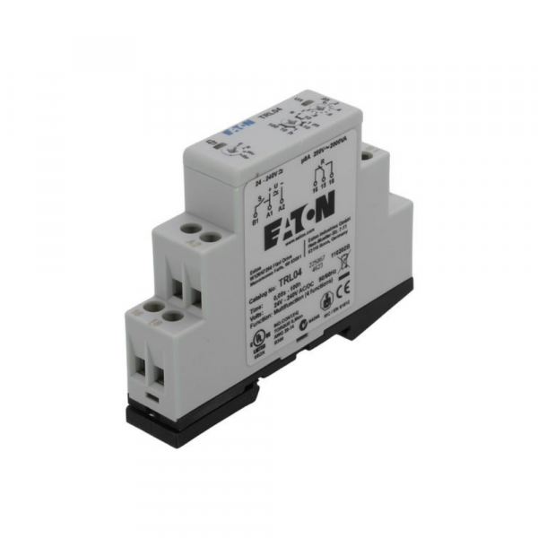
Cutler Hammer-Eaton TRL04 SPDT Timing Relay 24 VAC/240 VDC

Special Price $154.54 Regular Price $177.73
In stock
SKU
TRL04
The Cutler Hammer-Eaton TRL04 Relay is an SPDT timing product used in different HVAC systems and functions properly in voltage ratings of 24VAC to 240 VDC. This relay works on the Concept of time delay control of circuits and is therefore suitable for use in starting and stopping equipment or controlling the cycles of a system. It has four programmable functions and the delay time range is from 0.05 seconds to 100 hours, which improves to the operation versatility. Frequently applied in HVAC systems for fans, compressors, and pumps, the enhances energy consumption and system performance by making certain that equipment runs only when required.
Manufacturer:

https://www.partshnc.com/media/catalog/product/t/r/trl04.jpg

Specifications

  • Type: SPDT Relay
  • Switch Type: SPDT
  • Voltage: 24VAC-240 VDC
Manufacturer Name: Cutler Hammer-Eaton
Product Number: TRL04
OEM Part Number: TRL04
Product Description: Spdt Relay 24-240V Ac/Dc
Weight:0.17lbs/77.11g

Choose the best HVAC equipment parts and supplies from PartsHnC!

  • Same Day Shipping

  • Best Quality And Best Price

  • Wide Range of Inventory

  • Best Customer Service

Have More Questions or Need Help to Place The Order?
Reach us at (866)773-0907 or [email protected]

Write Your Own Review
You're reviewing:Cutler Hammer-Eaton TRL04 SPDT Timing Relay 24 VAC/240 VDC
Your Rating
Customer Questions
What maintenance is required for the Cutler Hammer-Eaton TRL04 Timing Relay?

Inspect wiring terminals regularly for looseness or corrosion and ensure secure connections. Keep the relay clean and free from dust accumulation to prevent overheating. Test timing accuracy periodically to ensure proper operation. Always isolate power before servicing for safety.

What are common issues with the Cutler Hammer-Eaton TRL04 Timing Relay?

  • Intermittent switching due to worn relay contacts.
  • Timing inaccuracies from voltage fluctuations or internal wear.
  • Coil failure caused by overload or incorrect supply.
  • Overheating due to Low ventilation or continuous heavy-duty operation.

Installation Steps

Step 1: Turn off power supply and verify zero voltage for safety before installation.

Step 2: Mount relay securely on rail or panel per wiring diagram as specified.

Step 3: Connect control voltage terminals to designated input terminals according to label markings.

Step 4: Wire load contacts to output terminals as per circuit requirements, ensuring correct polarity where applicable.

Step 5: Restore power and test timing operation, adjust settings if needed, monitor operation for correct timing response.