
Facebook Pixel

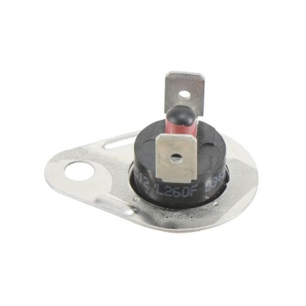
Trane SWT04163 Flame Rollout Switch

Special Price $10.96 Regular Price $14.25
In stock
SKU
SWT04163
The Trane SWT04163 Flame Rollout Switch monitors abnormal flame or heat conditions within a furnace heating assembly. It responds when excessive temperature reaches the rollout area, opening the electrical circuit to interrupt burner operation and limit further heating. In HVAC systems, this switch is positioned near the burner compartment or heat exchanger section where flame rollout can be detected. Its electrical contacts interact with the furnace control circuit, allowing heating operation to stop when the temperature condition occurs. The component is used in heating equipment to provide temperature-based protection during burner operation and assist in maintaining proper safety control within the heating system.
https://www.partshnc.com/media/catalog/product/s/w/swt04163_1.jpg

Specifications

  • Type: Flame Rollout Switch
    Write Your Own Review
    You're reviewing:Trane SWT04163 Flame Rollout Switch
    Your Rating
    Customer Questions
    What maintenance is required for the Trane SWT04163 Flame Rollout Switch?

    Regularly inspect the switch for soot, corrosion, or loose wiring connections. Clean the surrounding area to prevent obstruction of the sensor. Proper maintenance ensures accurate flame detection and prevents unsafe burner operation.

    What are common issues with the Trane SWT04163 Flame Rollout Switch?

    • Switch failing to detect flame.
    • Frequent or false trips.
    • Corrosion or buildup on the contacts.
    • Intermittent electrical connection issues.

    Installation Steps

    Step 1: Turn off power at the breaker to prevent electrical shock.

    Step 2: Remove any covering or panel to access the existing switch.

    Step 3: Disconnect wires from the old switch, noting their positions.

    Step 4: Remove the old switch and install the new switch in the same location.

    Step 5: Reconnect wires to the terminals following the original configuration.

    Step 6: Restore power and test the switch for proper operation.