
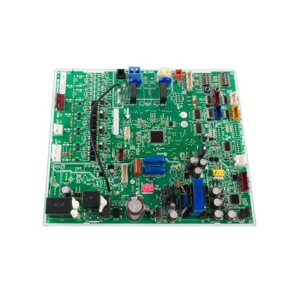
Mitsubishi Electric T7WM14315 Control Printed Circuit Board
Special Price $490.92 Regular Price $544.93
In stock
SKU
T7WM14315

The Mitsubishi Electric T7WM14315 Control Printed Circuit Board is a component that is used in HVAC systems to control and oversee many operations for the better efficiency. The roles of a Control PCB are to read the outputs of the sensors and the inputs from the users to regulate the operations of HVAC systems. It conserves costs of energy and maintains consistent indoor climate as it has control of factors such as temperature, fan and compressor operation. The PCB is mounted in Mitsubishi Electric HVAC devices, including air conditioners and heat pumps, to facilitate communication between different components.

Specifications
- Weight:1.08lbs
- Material: FR4 fire-resistant fiberglass
- Type: Control PCB
- Length: 7-1/2"
- Width: 8-3/4"