
Facebook Pixel

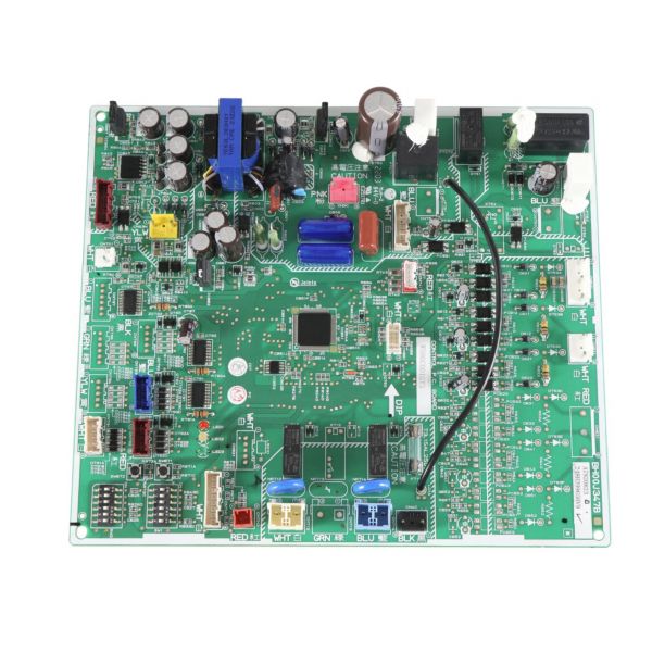
Mitsubishi Electric T7WM13315 Printed Circuit Board

Special Price $490.92 Regular Price $544.93
In stock
SKU
T7WM13315
The Mitsubishi Electric T7WM13315 is a high accuracy PC board for outdoor control in HVAC systems. This complex board is effective in maintaining and improving the system functions. Its structure makes it durable and the sleek design also enables precision in the regulation of many HVAC functions. This small but effective component is essential for Mitsubishi Electric HVAC equipment’s performance and comfort and energy-saving advantages.

https://www.partshnc.com/media/catalog/product/T/7/T7WM13315_MitsubishiElectric_partshnc.jpg

Specifications

  • Type: PC Board
  • Design: Advanced design for precise control
  • Function: Outdoor control
  • Weight:1.05lbs
Manufacturer Name: Mitsubishi Electric
Product Number: T7WM13315
OEM Part Number: T7WM13315
Product Description: Pc Board
Weight:1.05lbs/476.27g

Choose the best HVAC equipment parts and supplies from PartsHnC!

  • Same Day Shipping

  • Best Quality And Best Price

  • Wide Range of Inventory

  • Best Customer Service

Have More Questions or Need Help to Place The Order?
Reach us at (866)773-0907 or [email protected]

Write Your Own Review
You're reviewing:Mitsubishi Electric T7WM13315 Printed Circuit Board
Your Rating
Customer Questions
What maintenance is required for the Mitsubishi Electric T7WM13315 Printed Circuit Board?

Regularly inspect the printed circuit board for dust, dirt, or signs of corrosion. Ensure all connectors are secure and solder joints intact. Avoid exposure to moisture or static discharge. Handle with care using anti-static precautions during inspections.

What are common issues with the Mitsubishi Electric T7WM13315 Printed Circuit Board?

  • Malfunctioning or unresponsive circuits.
  • Burned or damaged components.
  • Loose or broken solder joints.
  • Corrosion or short circuits from moisture.

Installation Steps

Step 1: Turn off all power to HVAC system and verify zero voltage.

Step 2: Remove access panel and carefully disconnect existing printed circuit board connectors.

Step 3: Insert new PCB into correct slot, ensuring firm alignment and secure seating.

Step 4: Reconnect wiring harnesses per labeling and service diagram.

Step 5: Restore power, run system test, and confirm stable operation without faults.