
Mitsubishi Electric T2WF2Y451 Control Board
Special Price $121.22 Regular Price $139.40
In stock
SKU
T2WF2Y451

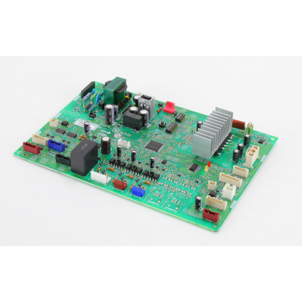
The Mitsubishi Electric T2WF2Y451 Control Board is an essential part utilized in the accurate management of the HVAC systems. This control board is capable of operating at temperatures up to 52°C for reliability in different conditions. This control board can be applied in most of the contemporary HVAC equipment which includes air conditioners and heat pumps to monitor and control the system. Its optimizes many facets, which ensures the operation, energy conservation, and comfort of the building. Due to accurate control of the airflow and the temperature, the energy efficiency of the AC system is enhanced and the durability of the equipment is also increased.
Manufacturer:

Specifications
- Temperature Range: 52°C
- Type: Control Board
- Length : 9"
- Width: 6 3/8"
- Height : 1 1/2"
- Weight: 0.87 Lbs