
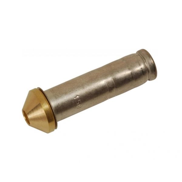
Danfoss 068-2010 Expansion Valve Orifice T2 Style No.01
Special Price $17.35 Regular Price $22.55
In stock
SKU
068-2010

The Danfoss 068-2010 T2 Style Orifice No.01 is for HVAC purposes and has an aspect ratio of 0.79 and is extremely accurate. This cavity has a receiving volume of 0.016 liters and orifice size of 01” to act as a control mechanism for refrigerant flow within the system. It has well RI with R22, R407C and R513A refrigerants, and thus well-suited to a broad range of services. This orifice is to be used at temperatures of 50 °F and below – 40°F. Likewise, proper charge of the refrigerant enhances the life of the HVAC equipment and raises the cop overall efficiency in the Danfoss 068-2010.
Manufacturer:

Specifications
- Weight:0.04 lbs
- Orifice size: 01"
- Volume: 0.016 Liter
- Refrigerants: R513A,R22/R407C
- Type: ORF
- Temperature Range: 50°F To -40°F