Facebook Pixel

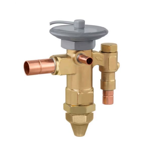
Sporlan Controls 164371 Thermostatic Expansion Valve

Special Price $304.49 Regular Price $337.98
In stock
SKU
164371
The Sporlan Controls 164371 Thermostatic Expansion Valve is an accurate metering pump of refrigerant applied in the HVAC systems and refrigeration to control the flow of refrigerant to the evaporation. It detects superheat at the outlet of evaporator and adjusts the flow of the refrigerant to the optimum heat exchange. The refrigerant line between the liquid line and the evaporator coil is fitted with a valve, which is used in conjunction with the compressor and evaporator to maintain the pressure and temperatures in the system. In practice, the TXV improves the work and prevents the submergence of coils.
https://www.partshnc.com/media/catalog/product/1/6/164371.jpg

Specifications

  • Type: Thermostatic Expansion Valve
  • Compatibility Model: EGSE-2-C
  • Capillary Length: 5'
  • Inlet Connection Size: 3/8"
  • OutletConnection Size: 1/2"
  • Capacity: 2Ton
Write Your Own Review
You're reviewing:Sporlan Controls 164371 Thermostatic Expansion Valve
Your Rating
Customer Questions
What maintenance is required for the Sporlan Controls 164371 Thermostatic Expansion Valve?

Regularly inspect the valve for leaks, corrosion, or debris buildup. Ensure proper refrigerant flow and that the sensing bulb is securely mounted. Clean surrounding components to prevent blockages. Proper maintenance helps maintain efficient cooling and stable system operation.

What are common issues with the Sporlan Controls 164371 Thermostatic Expansion Valve?

  • Restricted or uneven refrigerant flow.
  • Leaking seals or connections.
  • Valve sticking or failing to modulate.
  • System pressure fluctuations affecting cooling performance.

Installation Steps

Step 1: Turn off power and isolate the refrigeration system before starting.

Step 2: Locate the liquid line where the valve will be installed and remove the existing fitting if necessary.

Step 3: Attach the valve to the line, ensuring proper alignment with flow direction markings.

Step 4: Connect the sensing bulb to the suction line, securing it with straps or clamps.

Step 5: Tighten all connections and check for leaks.

Step 6: Restore system power and monitor operation.