Facebook Pixel

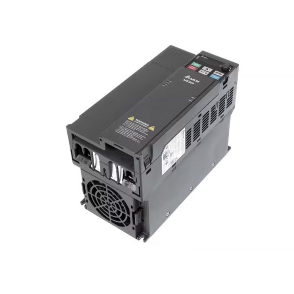
York S1-6112154 15HP VFD Controller 480V/3PH 18.9A

Special Price $2,138.28 Regular Price $2,373.49
Out of stock
SKU
S1-6112154
The York S1-6112154 VFD controller, has a horsepower rating of 15HP and works on a 480V 3-phase power supply, and has an 18.9A current rating. As a VFD controller, it uses the speed of AC motors by controlling the frequency and voltage supplied and controlling the motor. This part is widely applied in HVAC systems to control the speed of load such as fan, pump compressor, etc. The following are the advantages that accrue from using this VFD in HVAC applications, energy efficiency is realized since the motor speed is adjusted to correspond with the required load, better control of temperature to meet comfort requirements, low noise levels since motor noise is reduced, and longer equipment life.
https://www.partshnc.com/media/catalog/product/s/1/s1-6112154-1.jpg

Specifications

  • Type: VFD Controller
  • Voltage: 480V
  • Phase: 3PH
  • Horsepower: 15HP
  • Current: 18.9A
Write Your Own Review
You're reviewing:York S1-6112154 15HP VFD Controller 480V/3PH 18.9A
Your Rating
Customer Questions
What maintenance is required for the York S1-6112154 VFD Controller?

Regularly inspect the controller for dust buildup, loose connections, and signs of overheating. Clean cooling fans and vents, and check programming settings periodically. Proper maintenance ensures efficient operation and prevents electrical faults. Always disconnect power before servicing.

What are common issues with the York S1-6112154 VFD Controller?

  • Overheating or fan failure.
  • Fault codes or operational errors.
  • Loose or damaged wiring.
  • Inconsistent motor speed or output.

Installation Steps

Step 1: Turn off power to the system and lock out all sources for safety.

Step 2: Remove the access panel and disconnect wiring from the old VFD controller.

Step 3: Mount the new controller securely in the same location.

Step 4: Reconnect input power and motor output wiring according to the manufacturer’s diagram.

Step 5: Verify all connections are tight and correctly labeled.

Step 6: Restore power and perform a test run to ensure proper motor control and operation.