Facebook Pixel

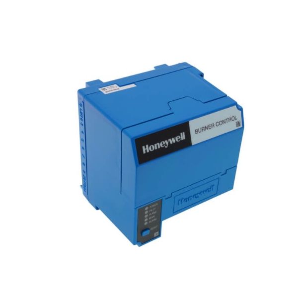
Honeywell RM7890A1015 Automatic Primary Control 4-10 Sec PFEP Lockout/Recycle On Flame Failure 120V

Special Price $658.53 Regular Price $730.97
In stock
SKU
RM7890A1015
The Honeywell RM7890A1015 On/Off Automatic Primary Burner Control 120V 4-10 Sec that is used to control gas, oil, or combination burners in commercial and industrial HVAC systems and is rated at 120V. It has a flame response time of 4-10 seconds. it supervises and controls the safety and ignition sequences of furnaces, boilers, and other heating equipment to ensure that the flame is burning safely and to detect faults. Advantages include increased safety of the system, increased efficiency of the system, and compatibility with existing HVAC systems.
Manufacturer:

https://www.partshnc.com/media/catalog/product/r/m/rm7890a1015.jpg
Manufacturer Name: Honeywell Thermal Solutions
Product Number: RM7890A1015
OEM Part Number: RM7890A1015
Product Description: Automatic Primary Control 4-10 Sec Pfep Lockout Or Recycle On Flame Failure 120V
Weight:3.5lbs/1587.57g

Choose the best HVAC equipment parts and supplies from PartsHnC!

  • Same Day Shipping

  • Best Quality And Best Price

  • Wide Range of Inventory

  • Best Customer Service

Have More Questions or Need Help to Place The Order?
Reach us at (866)773-0907 or [email protected]

Write Your Own Review
You're reviewing:Honeywell RM7890A1015 Automatic Primary Control 4-10 Sec PFEP Lockout/Recycle On Flame Failure 120V
Your Rating
Customer Questions
What maintenance is required for the Honeywell RM7890A1015 Automatic Primary Control?

Inspect wiring harness connections and keep the control module dry and clean. Verify flame detection timing and safety lockout action during burner startup. Routine checks support proper combustion supervision and proper shutdown response when flame conditions change.

What are common issues with the Honeywell RM7890A1015 Automatic Primary Control?

  • Unexpected safety lockout.
  • Flame signal not detected.
  • Startup sequence failing.
  • Recycle timing becoming inconsistent.
  • Control module overheating.

Installation Steps

Step 1: Turn off power supply to the burner system for safety.

Step 2: Mount the control securely on a compatible sub-base.

Step 3: Connect wiring according to the manufacturer’s wiring diagram.

Step 4: Attach flame sensor and ignition components properly.

Step 5: Restore power and configure timing/settings if required.

Step 6: Test the system for proper startup and flame detection.

Step 7: Ensure all connections are secure and follow electrical safety guidelines.