Facebook Pixel

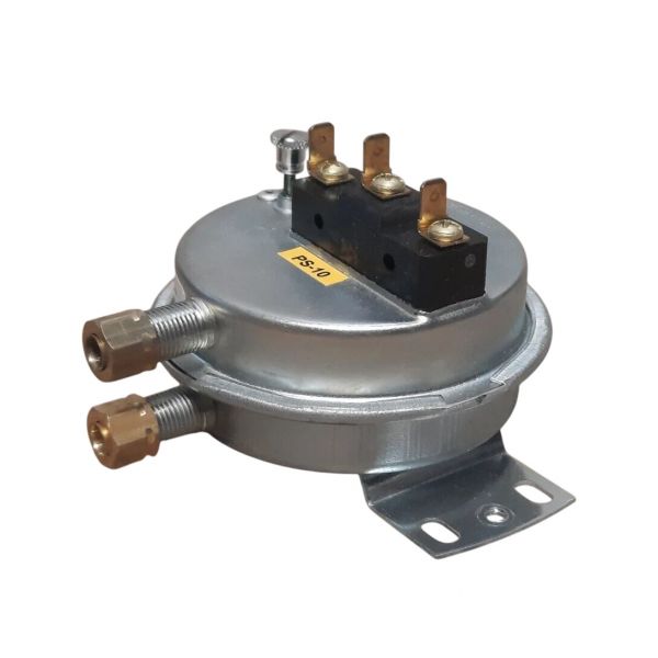
Cleveland Controls RFS-4100-078 0.17" Low Air Flow Switch

Special Price $70.30 Regular Price $80.85
In stock
SKU
RFS-4100-078
The Cleveland Controls RFS-4100-078 Low Air Flow Switch is a pressure-acting safety system that is utilized to sense when a HVAC systems. This switch operates to close or open an electrical circuit when the difference in air pressure exceeds 0.17" water column, which means Low airflow conditions may affect heat exchange and the overall performance of the system. It is installed in furnaces, air handlers or duct systems as part of the airflow monitoring and safety sequence to assist in preventing overheating.
https://www.partshnc.com/media/catalog/product/r/f/rfs-4100-078.jpg
Manufacturer Name: Cleveland Controls
Product Number: RFS-4100-078
OEM Part Number: RFS-4100-078
Product Description: .17" Low Air Flow Switch
Weight:0.53lbs/240.4g

Choose the best HVAC equipment parts and supplies from PartsHnC!

  • Same Day Shipping

  • Best Quality And Best Price

  • Wide Range of Inventory

  • Best Customer Service

Have More Questions or Need Help to Place The Order?
Reach us at (866)773-0907 or [email protected]

Write Your Own Review
You're reviewing:Cleveland Controls RFS-4100-078 0.17" Low Air Flow Switch
Your Rating
Customer Questions
What maintenance is required for the Cleveland Controls RFS-4100-078 Air Flow Switch?

Regularly inspect pressure sensing ports and tubing for dust or blockage and ensure tight connections. Clean gently with dry air if needed. Periodic calibration checks help maintain accuracy. Proper maintenance ensures accurate airflow detection and prevents false triggering.

What are common issues with the Cleveland Controls RFS-4100-078 Air Flow Switch?

  • Clogged pressure ports causing inaccurate readings.
  • Loose or damaged tubing connections.
  • Intermittent switching or false alarms.
  • Sensor drift leading to calibration errors.
  • Blocked sensing lines.

Installation Steps

Step 1: Turn off HVAC power and apply lockout/tagout; check zero voltage before working.

Step 2: Mount the switch in the duct or air handler using the connection, ensuring correct airflow direction.

Step 3: Connect sensing tubes to high and low pressure ports, keeping lines free of leaks or kinks.

Step 4: Wire terminals per control circuit diagram and secure all connections.

Step 5: Restore power and test by confirming proper switching at airflow differential.