Facebook Pixel

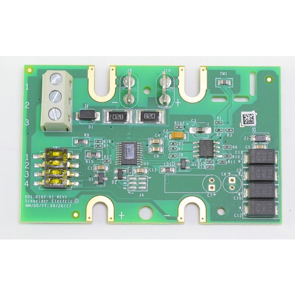
Schneider Electric (Viconics) R820-PCB-A01 Multi-Signal Input Board

Special Price $152.37 Regular Price $175.23
In stock
SKU
R820-PCB-A01
The Schneider Electric (Viconics) R820-PCB-A01 Multi-Signal Input Board is an electronic interface that accepts and processes a set of input signals of sensors and control HVAC systems. It is mounted in controllers, air handlers, and rooftop units to check temperature, pressure or any other operational parameter. These signals are translated by the board to actionable data to manage the system and make correct adjustments to the heating, cooling, and ventilation systems. It ensures the coordinated work of sensors and control modules, enables the accurate regulation of the environment, and leads to the effective work.

https://www.partshnc.com/media/catalog/product/R/8/R820-PCB-A01_SchneiderElectric_Viconics__partshnc.jpg
Manufacturer Name: Schneider Electric (Viconics)
Product Number: R820-PCB-A01
OEM Part Number: R820-PCB-A01
Product Description: Multi-Signal Input Board
Weight:0.11lbs/49.9g

Choose the best HVAC equipment parts and supplies from PartsHnC!

  • Same Day Shipping

  • Best Quality And Best Price

  • Wide Range of Inventory

  • Best Customer Service

Have More Questions or Need Help to Place The Order?
Reach us at (866)773-0907 or [email protected]

Write Your Own Review
You're reviewing:Schneider Electric (Viconics) R820-PCB-A01 Multi-Signal Input Board
Your Rating
Customer Questions
What maintenance is required for the Schneider Electric (Viconics) R820-PCB-A01 Multi-Signal Input Board?

Regularly inspect the board for dust, debris, and loose connections. Ensure all signal terminals are tight and corrosion-free. Avoid exposure to moisture, and power down the system before servicing to prevent electrical hazards.

What are common issues with the Schneider Electric (Viconics) R820-PCB-A01 Multi-Signal Input Board?

  • Intermittent signal readings.
  • Loose or corroded terminal connections.
  • Overheating due to poor ventilation.
  • Incorrect input mapping or wiring errors.

Installation Steps

Step 1: Power off HVAC and isolate mains supply at breaker.

Step 2: Use ESD protection and open control enclosure carefully.

Step 3: Mount board on designated standoffs, align connectors securely.

Step 4: Connect input wiring per labeled terminals and wiring schematic.

Step 5: Secure screws, check terminal torque, verify polarity correctness.

Step 6: Restore power and test signal inputs for correct operation, monitor for faults.