Facebook Pixel

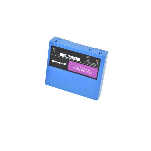
Honeywell Thermal Solutions R7849A1015 Ultraviolet Flame Amplifier 0.8 Sec FFRT

Special Price $313.21 Regular Price $347.66
In stock
SKU
R7849A1015
The Honeywell Thermal Solutions R7849A1015 Ultraviolet Flame Amplifier FFRT is an optical flame detector module installed in HVAC combustion systems to detect the presence of flame by the use of ultraviolet sensors. It checks the burner operation and gives a feedback signal to the control board in the given 0.8s flame failure response time, which makes sure that the system reacts properly to safe or unsafe conditions. It is installed in gas furnaces, boilers or other heating units and connects with the ignition control.
https://www.partshnc.com/media/catalog/product/r/7/r7849a1015.jpg
Manufacturer Name: Honeywell Thermal Solutions
Product Number: R7849A1015
OEM Part Number: R7849A1015
Product Description: Ultraviolet Rectification Amplifier 0.8 Second Flame Failure Response Time *** R
Weight:0.300000011920929lbs/136.08g

Choose the best HVAC equipment parts and supplies from PartsHnC!

  • Same Day Shipping

  • Best Quality And Best Price

  • Wide Range of Inventory

  • Best Customer Service

Have More Questions or Need Help to Place The Order?
Reach us at (866)773-0907 or [email protected]

Write Your Own Review
You're reviewing:Honeywell Thermal Solutions R7849A1015 Ultraviolet Flame Amplifier 0.8 Sec FFRT
Your Rating
Customer Questions
What maintenance is required for the Honeywell Thermal Solutions R7849A1015 UV Rectification Amplifier?

Inspect the amplifier regularly for proper installation and secure connections. Keep the module free from dust and moisture. Verify compatibility with the flame sensor and test flame detection response during routine servicing to ensure proper burner safety and efficient operation.

What are common issues with the Honeywell Thermal Solutions R7849A1015 UV Rectification Amplifier?

  • Failure to detect flame signals.
  • False flame detection or shutdowns.
  • Burner lockout conditions.
  • Intermittent amplifier communication.

Installation Steps

Step 1: Turn off all power to the burner control system to prevent electrical shock.

Step 2: Remove the old amplifier from the control chassis if replacing.

Step 3: Align the new amplifier with the slot and firmly insert it into the base.

Step 4: Ensure proper seating and secure connections.

Step 5: Restore power and test system operation for correct flame detection.