Facebook Pixel

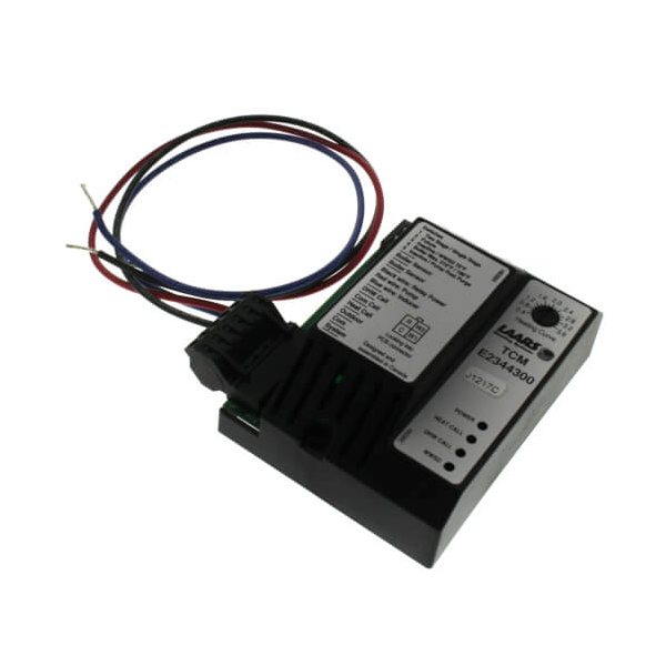
Laars Heating Systems RE2344300 PCB Temperature Control Module

Special Price $304.31 Regular Price $337.79
In stock
SKU
RE2344300
The Laars Heating Systems RE2344300 PCB Temperature Control Module is an electronic board that controls the sequencing and temperature in hydronic and forced-air HVAC systems. It receives the input of temperature sensors and translates setpoint and safety signals to burner, pump, and fan output commands. It comes in a unit that can be used in boilers and other compatible HVAC units and can be utilized safely in the control compartment and attached to field wiring harnesses. This module improves the ability of the system, provides continuous temperature delivery, and ensures the stable operation of the system.

https://www.partshnc.com/media/catalog/product/r/e/re2344300_laars-heating-systems_partshnc.png
Manufacturer Name: Laars Heating Systems
Product Number: RE2344300
OEM Part Number: RE2344300
Product Description: Pcb Temp Control Module
Weight:0.59lbs/267.62g

Choose the best HVAC equipment parts and supplies from PartsHnC!

  • Same Day Shipping

  • Best Quality And Best Price

  • Wide Range of Inventory

  • Best Customer Service

Have More Questions or Need Help to Place The Order?
Reach us at (866)773-0907 or [email protected]

Write Your Own Review
You're reviewing:Laars Heating Systems RE2344300 PCB Temperature Control Module
Your Rating
Customer Questions
What maintenance is required for the Laars Heating Systems RE2344300 PCB Temperature Control Module?

Keep the module free from dust and moisture by regularly inspecting the enclosure. Check wiring terminals for tightness, corrosion, and heat damage. Periodically test the control board for safe operation.

What are common issues with the Laars Heating Systems RE2344300 PCB Temperature Control Module?

  • Sensor calibration drift causing inaccurate temperature control.
  • Control board failure due to electrical surges.
  • Intermittent power loss or reset issues.
  • Communication errors with heating system components.
  • Relay or switching malfunctions affecting operation.

Installation Steps

Step 1: Turn off power and shut down the unit completely.

Step 2: Remove front panel and label all wiring connections.

Step 3: Disconnect wiring harness from old board carefully.

Step 4: Unscrew and remove the faulty PCB control module.

Step 5: Mount the new PCB control module in the same position securely.

Step 6: Reconnect all terminals exactly as originally wired.

Step 7: Restore power and run the system.