Facebook Pixel

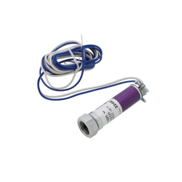
Honeywell C7027A1031 1/2" Minipeeper UV Sensor -40°F

Special Price $317.99 Regular Price $352.97
In stock
SKU
C7027A1031
The Honeywell C7027A1031 Minipeeper Ultraviolet Sensor functions as a dependable flame detection product for gas-fired equipment to enable secure and efficient burner operation. This compact 1/2" sensor functions in commercial and industrial HVAC systems to detect ultraviolet radiation from flames for preventing hazardous situations. Because it operates at temperatures reaching -40°F this part delivers reliable durability and stability. This product serves boilers and furnaces by improving safety measures and system efficiency and operational reliability.
https://www.partshnc.com/media/catalog/product/c/7/c7027a1031_1.jpg
Manufacturer Name: Honeywell
Product Number: C7027A1031
OEM Part Number: C7027A1031
Product Description: Minipeeper Uv Sensor -40F,1/2"
Weight:0.51lbs/231.33g

Choose the best HVAC equipment parts and supplies from PartsHnC!

  • Same Day Shipping

  • Best Quality And Best Price

  • Wide Range of Inventory

  • Best Customer Service

Have More Questions or Need Help to Place The Order?
Reach us at (866)773-0907 or [email protected]

Write Your Own Review
You're reviewing:Honeywell C7027A1031 1/2" Minipeeper UV Sensor -40°F
Your Rating
Customer Questions
What maintenance is required for the Honeywell C7027A1031 UV Sensor?

Inspect the UV sensor lens regularly for soot, dust, or oil buildup that can reduce flame detection accuracy. Clean gently with a soft lint-free cloth and approved cleaner. Ensure wiring connections are tight and free from corrosion or heat damage.

What are common issues with the Honeywell C7027A1031 UV Sensor?

  • Dirty or obstructed lens causing weak flame signal.
  • Loose wiring leading to intermittent flame detection.
  • Misalignment with flame source reducing sensitivity.
  • Electrical noise interference affecting signal stability.
  • Cracked housing or moisture ingress causing failure.

Installation Steps

Step 1: Isolate power to burner control panel to prevent electric shock.

Step 2: Mount sensor securely near burner sighting port ensuring clear line of sight to flame.

Step 3: Align UV tube correctly and tighten bracket avoid exposure to UV or hot surfaces.

Step 4: Connect wiring to terminals per diagram ensuring tight correct polarity connections.

Step 5: Secure housing restore power and test flame signal for stable operation and safety.