Facebook Pixel

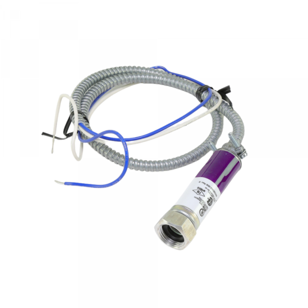
Honeywell C7027A1114 Minipeeper Uv Sensor

Special Price $306.27 Regular Price $339.96
In stock
SKU
C7027A1114

The Honeywell C7027A1114 Minipeeper Ultraviolet Sensor is an essential component in HVAC systems that detects the presence of flames in combustion chambers. This sensor senses the ultraviolet radiation released by flames during combustion using the ultraviolet light detection technique. This sensor is designed specifically to be used with heating, ventilation, and air conditioning equipment, which includes burners, boilers, and furnaces. It improves safety by quickly determining if a flame is present or not. Its small size makes installation simple in a range of HVAC setups. The integration of the Honeywell C7027A1114 Minipeeper UV Sensor yields several advantages, such as increased operational efficiency, enhanced safety protocols, and improved system dependability, which guarantee the safe and seamless functioning of HVAC systems in various settings. 



https://www.partshnc.com/media/catalog/product/c/7/c7027a1114_1.png
MINIPEEPER UV SENSOR for Honeywell PART# C7027A1114
Write Your Own Review
You're reviewing:Honeywell C7027A1114 Minipeeper Uv Sensor
Your Rating
Customer Questions
What maintenance is required for the Honeywell C7027A1114 UV Sensor?

Keep the sensing window clean so ultraviolet flame radiation can be detected without obstruction. Periodically wipe the lens using a soft, non-abrasive cloth to remove soot or oil film. Inspect wiring connections for tightness and signs of heat damage or corrosion.

What are common issues with the Honeywell C7027A1114 UV Sensor?

  • Intermittent flame detection from misalignment with burner flame.
  • Loose wiring causing erratic or lost signal feedback.
  • Electrical interference affecting sensor stability and readings.
  • Moisture or heat damage leading to internal component failure.

Installation Steps

Step 1: Switch off power and isolate burner system before handling sensor.

Step 2: Mount UV Sensor on sighting tube aligned with flame.

Step 3: Secure bracket and ensure proper viewing angle of flame.

Step 4: Connect wiring to control module per diagram.

Step 5: Restore power and test flame signal, verify stable ignition and shut down if unsafe.