
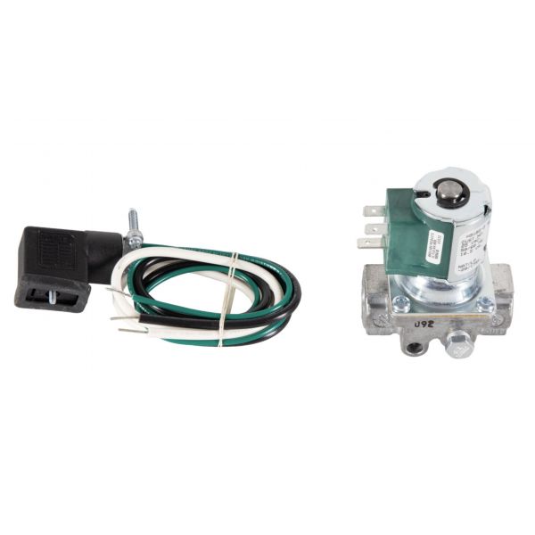
BASO Gas Products H91BG-2C REVB 1/4" Gas Valve 100,000BTU 24V
Specifications
- Type: Gas Valve
- Connection Size: 1/4" NPT
- Voltage: 24V
- Capacity: 100,000 BTU
Loyalty ProgramProduct Overview:
Regulates fuel delivery in applicable heating equipment using a 24V electrical specification. The BASO Gas Products H91BG-2C REVB 1/4" Gas Valve 100K BTU 24V features a 1/4" connection size and a 100K BTU capacity rating. Its electrical control function manages gas flow within the heating system according to the equipment's operating demand.
Electrical-to-Gas Control:
The gas valve responds to the equipment's electrical control sequence to regulate gas passage. The valve connects the control circuit with the fuel supply path, allowing the control signal to actuate the internal valve mechanism. This coordinates gas admission with the equipment's operating demand and interrupts the fuel path when the operating command is removed.
Replacement Guidelines:
Replacement may be appropriate when the BASO Gas Products H91BG-2C REVB 1/4" Gas Valve 100K BTU 24V shows physical deterioration or damage affecting the assembly. Relevant conditions may include a damaged valve body, deteriorated connection areas, corrosion, or other physical damage.
Common Failure Symptoms:
Equipment Compatibility:
The BASO Gas Products H91BG-2C REVB 1/4" Gas Valve 100K BTU 24V is specified for gas-fired heating equipment requiring a 24V gas valve with a 1/4" connection and 100K BTU capacity rating. Verify the equipment model, existing valve part number, fuel type, connection arrangement, and applicable control requirements against manufacturer documentation before selecting the valve.
Technical Specifications:
Brand: BASO Gas Products
Part Number: H91BG-2C REVB
Product Type: Gas Valve
Connection Size: 1/4"
Capacity Rating: 100K BTU
Voltage: 24V
Step 1: Turn off gas supply and disconnect electrical power.
Step 2: Allow the system to cool before starting installation.
Step 3: Remove the faulty gas valve and clean the pipe threads.
Step 4: Install the new valve, ensuring correct flow direction.
Step 5: Secure fittings and reconnect wiring properly.
Step 6: Restore gas and power, then check for leaks and proper operation.