Facebook Pixel

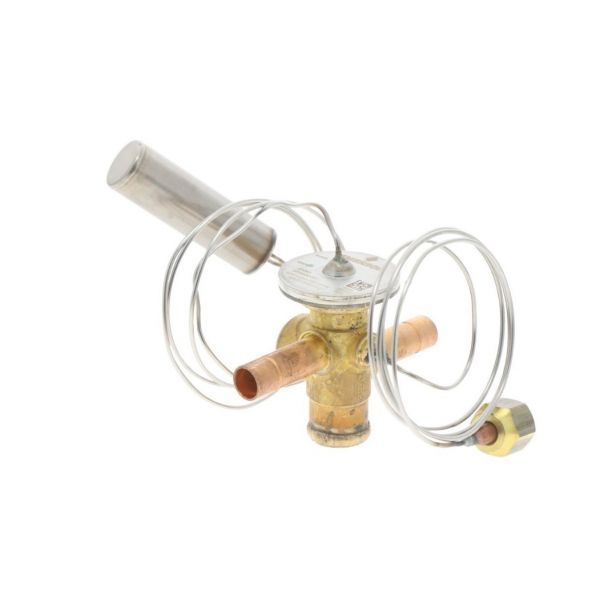
First Company CP7324 3/8" x 3/8" Thermal Expansion Valve(TXV) R410A

Special Price $226.89 Regular Price $251.85
In stock
SKU
CP7324
The First Company CP7324 Thermal Expansion Valve is used to regulate the flow of refrigerant into evaporator coil in cooling equipment in HVAC systems. The liquid refrigerant flowing past the valve is forced to undergo a controlled pressure drop, which then enables it to expand before passing into the evaporator space, the area in systems where the refrigerant absorbs heat. It will be used between the liquor line and evaporator inlet with 3/8" connections and designed to use R410A refrigerant. It is located in the refrigerant circuit and ensures a regulated refrigerant flow needed to provide consistent heat exchange.
Manufacturer:

https://www.partshnc.com/media/catalog/product/c/p/cp7324_1.jpg

Specifications

  • Type: Expansion Valve
  • Size: 3/8" x 3/8"
Write Your Own Review
You're reviewing:First Company CP7324 3/8" x 3/8" Thermal Expansion Valve(TXV) R410A
Your Rating
Customer Questions
What maintenance is required for the First Company CP7324 Thermal Expansion Valve?

Regularly inspect the valve for leaks, corrosion, or blockages. Ensure proper refrigerant flow and clean surrounding components. Verify that connections are tight and secure. Proper maintenance helps maintain efficient cooling and prevents system performance issues.

What are common issues with the First Company CP7324 Thermal Expansion Valve?

  • Restricted or uneven refrigerant flow.
  • Leaking connections or seals.
  • Valve sticking or not modulating properly.
  • System pressure fluctuations affecting cooling performance.

Installation Steps

Step 1: Turn off all power and recover refrigerant from the system before installation.

Step 2: Remove the existing TXV if replacing, ensuring the lines are clean and dry.

Step 3: Position the new valve in the liquid and suction line connections, aligning inlet and outlet ports.

Step 4: Braze or flare connections as required, avoiding overheating the valve bulb.

Step 5: Secure the sensing bulb to the suction line with proper orientation.

Step 6: Evacuate the system, recharge refrigerant, restore power, and test for proper operation.