Facebook Pixel

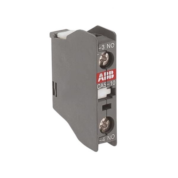
ABB CA5-10 Auxiliary Contact

Special Price $39.27 Regular Price $51.05
In stock
SKU
CA5-10
The ABB CA5-10 Auxiliary Contact Block is an electrical component that is intended to increase the capabilities of contactors in HVAC systems. This is a 1 pole block with 1 NO contact, it is rated for a current of 10A and a voltage of 600V AC. It makes it possible to increase the number of control circuits, which in turn makes it possible to perform more complicated operations given by the extra electrical contacts. It is front mounted and the block has screw terminals to allow easy connection of the system. Advantages include better circuit control, high voltage performance stability, and suitability for use with ABB’s A-series contactors.
Manufacturer:

https://www.partshnc.com/media/catalog/product/c/a/ca5-10.jpg

Specifications

  • Type: Auxiliary Contact Block
  • No of Poles: 1
  • Auxiliary Contact: 1N/O
  • Current: 10A
  • Voltage: 600 VAC
Manufacturer Name: ABB
Product Number: CA5-10
OEM Part Number: CA5-10
Product Description: Abb Auxiliary Contact
Weight:0.03lbs/13.61g

Choose the best HVAC equipment parts and supplies from PartsHnC!

  • Same Day Shipping

  • Best Quality And Best Price

  • Wide Range of Inventory

  • Best Customer Service

Have More Questions or Need Help to Place The Order?
Reach us at (866)773-0907 or [email protected]

Write Your Own Review
You're reviewing:ABB CA5-10 Auxiliary Contact
Your Rating
Customer Questions
What maintenance is required for the ABB CA5-10 Auxiliary Contact?

Regular inspection and cleaning of contacts and terminals is required to ensure accurate switching. This prevents oxidation and poor connectivity. Always de-energize the circuit before servicing, and check for tight connections and mechanical alignment to ensure safe operation.

What are common issues with the ABB CA5-10 Auxiliary Contact?

  • Contact wear or pitting causing inconsistent switching.
  • Terminal loosening leading to intermittent signals.
  • Oxidation buildup reducing conductivity.
  • Mechanical sticking or delayed response.
  • Misalignment of contacts affecting proper connection.

Installation Steps

Step 1: Switch off all control panel power and check zero voltage before handling.

Step 2: Mount onto a compatible to remove old contactor rail, ensuring firm mechanical connection.

Step 3: Align new auxiliary contact correctly with main contactor side slots.

Step 4: Snap into place and secure locking mechanism.

Step 5: Wire terminals according to control diagram, tightening connections properly.

Step 6: Restore power and test switching operation; confirm accurate auxiliary signal before closing panel.