Facebook Pixel

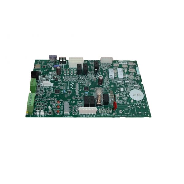
Amana-Goodman PCBKF109FS PCB Service Control Board

Special Price $252.00 Regular Price $279.72
Out of stock
SKU
PCBKF109FS
The Amana-Goodman PCBKF109FS PCB Service Control Board is an electronic control component used in matched furnaces to coordinate and manage overall unit operation. It processes incoming signals from thermostats and system sensors, then distributes output commands such as the blower assembly, ignition system, and gas valve based on operating logic. It maintains structured sequencing of startup, runtime, and shutdown while ensuring proper communication between connected parts. In HVAC systems, it is installed inside the furnace electrical compartment, where it control, system responses, and coordinated the operation.
https://www.partshnc.com/media/catalog/product/p/c/pcbkf109fs_1.jpg

Specifications

  • Type: Service PCB Control Board
  • Voltage: 24V AC
Write Your Own Review
You're reviewing:Amana-Goodman PCBKF109FS PCB Service Control Board
Your Rating
Customer Questions
What maintenance is required for the Amana-Goodman PCBKF109FS Control Board?

Regularly inspect the control board for dust, moisture, or loose wiring connections. Use compressed air to clean debris and ensure terminals are secure. Proper maintenance prevents signal errors and system malfunctions, keeping the HVAC system operating safely and accurately.

What are common issues with the Amana-Goodman PCBKF109FS Control Board?

  • System fails to start or respond.
  • Erratic or intermittent HVAC operation.
  • Burnt or damaged circuit traces.
  • Faulty sensor signal readings.

Installation Steps

Step 1: Turn off power to the HVAC system to prevent electrical shock.

Step 2: Locate the existing PCB control board and carefully disconnect all wiring and connectors.

Step 3: Remove the old board by unscrewing or unclipping it from its mounting.

Step 4: Install the new PCB in the same position, ensuring all connectors align correctly.

Step 5: Reconnect wiring following the original configuration or wiring diagram.

Step 6: Secure the board to prevent movement or loose connections.

Step 7: Restore power and test system operation.