
Facebook Pixel

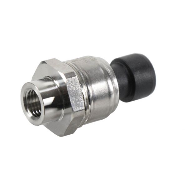
Sporlan Controls 993291 Pressure Transducer 0-150 PSI PSPT0150AVSP-SD

Special Price $299.44 Regular Price $332.38
Out of stock
SKU
993291
The Sporlan Controls 993291 Pressure Transducer is a control element used to monitor pressure signals in HVAC systems. It works under a certain pressure of up to 150 PSI, and it can be used in many applications that include refrigerators and heating and ventilation systems. This particular model is called PSPT0150AVSP-SD and its work is based on the conversion of pressure variations into an electrical signal that can be processed by a control system. This facilitates close supervision of pressure within the system and optimal operation of the system to high energy efficiency and increased safety due to early identification of possible pressure issues in the system. It finds application in almost all types of HVAC equipment such as refrigeration systems, heat pumps, and chillers.
https://www.partshnc.com/media/catalog/product/9/9/993291.jpg

Specifications

  • Type: Pressure Transducer
  • Pressure Range: 0-150 PSI
  • Model: PSPT0150AVSP-SD
Write Your Own Review
You're reviewing:Sporlan Controls 993291 Pressure Transducer 0-150 PSI PSPT0150AVSP-SD
Your Rating
Customer Questions
What maintenance is required for the Sporlan Controls 993291 Pressure Transducer?

Regularly inspect the transducer for leaks, corrosion, or loose connections. Clean the sensor and surrounding area to prevent debris interference. Verify readings periodically to ensure accuracy, and handle with care when disconnecting to avoid damaging delicate components.

What are common issues with the Sporlan Controls 993291 Pressure Transducer?

  • Inaccurate or fluctuating pressure readings.
  • Sensor drift over time.
  • Electrical connection failures.
  • Pressure spikes causing false alerts.

Installation Steps

Step 1: Turn off system power and relieve pressure.

Step 2: Mount the transducer securely to a compatible port using proper thread sealant.

Step 3: Connect electrical wiring as per wiring diagram.

Step 4: Verify connections are tight and free from leaks.

Step 5: Restore power and test system operation.