Facebook Pixel

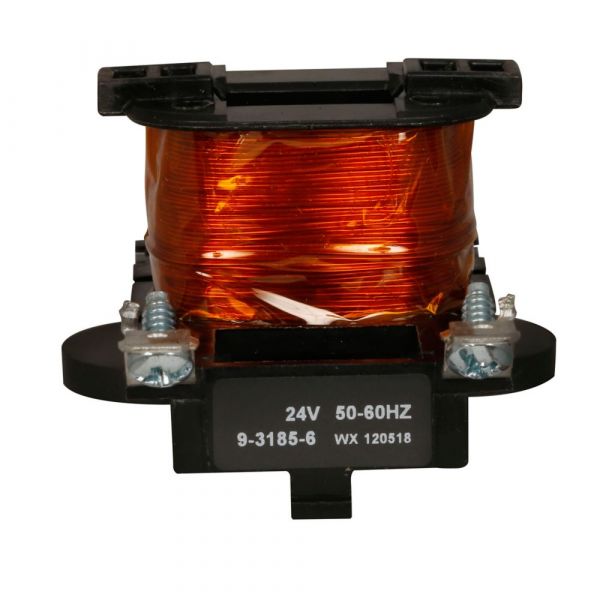
Cutler Hammer-Eaton 9-3185-2 Coil 208/240V 25-40A

Special Price $66.28 Regular Price $76.22
In stock
SKU
9-3185-2
The Cutler Hammer-Eaton 9-3185-2 Coil is an electromagnetic control component used in contactors and motor starters to initiate switching action within electrical circuits. When energized by a 208/240V control signal, it generates a magnetic field that pulls the contact mechanism into position, allowing current flow through the connected load circuit. Designed for use with 2540A contactor assembly supports control-led operation of motors, compressors, and other powered equipment. Within HVAC systems, this component assists in circuit activation, coordinated equipment control, and stable switching performance during startup and normal operating conditions.
https://www.partshnc.com/media/catalog/product/9/-/9-3185-2_cutler-hammer-eaton_partshnc.png
Manufacturer Name: Cutler Hammer-Eaton
Product Number: 9-3185-2
OEM Part Number: 9-3185-2
Product Description: 208/240V 25-40A Coil
Weight:0.19lbs/86.18g

Choose the best HVAC equipment parts and supplies from PartsHnC!

  • Same Day Shipping

  • Best Quality And Best Price

  • Wide Range of Inventory

  • Best Customer Service

Have More Questions or Need Help to Place The Order?
Reach us at (866)773-0907 or [email protected]

Write Your Own Review
You're reviewing:Cutler Hammer-Eaton 9-3185-2 Coil 208/240V 25-40A
Your Rating
Customer Questions
What maintenance is required for the Cutler Hammer-Eaton 9-3185-2 Coil?

Regular inspection of electrical connections and coil terminals ensures stable performance. Clean dust and debris buildup to prevent overheating or resistance issues. Check for signs of insulation wear or discoloration. Proper tightening and periodic testing improve accuracy and reduce unexpected electrical failures in operation.

What are common issues with the Cutler Hammer-Eaton 9-3185-2 Coil?

  • Coil overheating due to continuous high load operation.
  • Loose or corroded terminals causing intermittent activation.
  • Burnout from voltage fluctuations or improper supply.
  • Reduced magnetic response leading to weak switching performance.
  • Insulation breakdown causing short circuits or failure.

Installation Steps

Step 1: Disconnect power at breaker and verify zero voltage.

Step 2: Remove cover and label existing wiring for reference before handling the coil assembly.

Step 3: Mount coil securely into contactor slot and align terminals, ensuring proper seating.

Step 4: Connect wires to matching terminals and tighten screws firmly to avoid loose connections.

Step 5: Restore power and test operation under load while monitoring for abnormal heat or noise.