Facebook Pixel

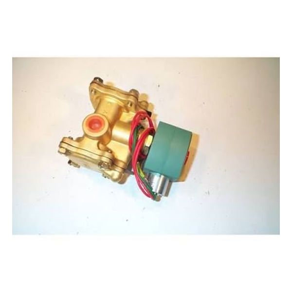
Asco 8316G14 3/8" 3-Way Normally Closed Solenoid Valve 10-250 PSI

Special Price $639.89 Regular Price $710.28
In stock
SKU
8316G14
The ASCO 8316G14 Solenoid valve is used to control air and water flow in different applications and it is a 3/8” 3-Way Normally Closed type. This valve is used in a pressure range of 10 to 250 PSI and remains closed until opened, which makes it useful in controlling the flow of fluids. It is mainly constructed from brass for general environment use and has resilient seats that provide tight shutoff for better reliability in HVAC system applications. Some of the advantages are short response time for the actuator control, low maintenance requirement due to the design, and integration with various automation systems.
Manufacturer:

https://www.partshnc.com/media/catalog/product/8/3/8316g14_asco_partshnc.jpg

Specifications

  • Type: Normally Closed Solenoid Valve
  • Size: 3/8"
  • Pressure Range: 10-250 PSI
Manufacturer Name: ASCO
Product Number: 8316G14
OEM Part Number: 8316G14
Product Description: 3/8" 3Way 10-250#Airwtr N/C
Weight:4.41lbs/2000.34g

Choose the best HVAC equipment parts and supplies from PartsHnC!

  • Same Day Shipping

  • Best Quality And Best Price

  • Wide Range of Inventory

  • Best Customer Service

Have More Questions or Need Help to Place The Order?
Reach us at (866)773-0907 or [email protected]

Write Your Own Review
You're reviewing:Asco 8316G14 3/8" 3-Way Normally Closed Solenoid Valve 10-250 PSI
Your Rating
Customer Questions
What maintenance is required for the Asco 8316G14 Solenoid Valve?

Check the valve for proper actuation and ensure electrical connections are secure. Clean internal passages to prevent buildup that may restrict flow. Inspect seals for wear or leakage. Routine checks support maintain accurate valve performance and system control.

What are common issues with the Asco 8316G14 Solenoid Valve?

  • Delayed or failed valve actuation.
  • Coil overheating or burnout.
  • Internal debris causing restricted flow.
  • Seal wear leading to leakage.

Installation Steps

Step 1: Disconnect power and depressurize system; confirm compatible fluid and safe working conditions.

Step 2: Install valve following flow direction arrow, use thread sealant, and tighten fittings securely.

Step 3: Wire terminals as per diagram, ensuring correct voltage and proper grounding.

Step 4: Restore pressure and energize system slowly, inspect for leaks and confirm proper actuation.