
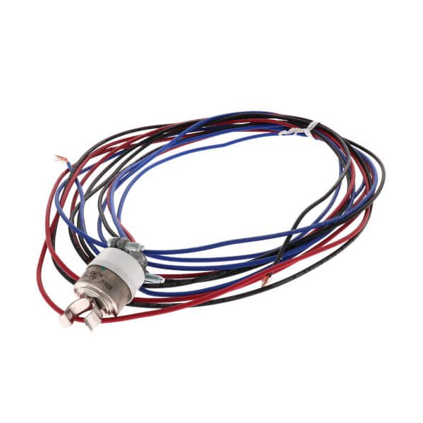
International Environmental 70011411 1/2" Aquastat 96" Lead L85-15F
Specifications
- Type: Aquastat
- Pipe Size: 1/2"
- Lead Length: 96"
- Temperature Range: 85°F - 15°F
Loyalty ProgramProduct Overview:
Temperature-responsive controls help equipment maintain operation according to its intended thermal conditions. The 70011411 Aquastat serves as an OEM replacement component for designated equipment. Its 1/2-inch size, 96-inch lead, and L85-15F designation define the configuration for applications requiring this aquastat.
Temperature Monitoring:
The aquastat responds to temperature conditions and provides the input needed for temperature-based control. This sensing action allows the connected equipment to respond according to its intended temperature requirements.
Connection and Lead Configuration
Features a 1/2-inch connection and a 96-inch lead. The extended lead provides flexibility for positioning the sensing component in relation to the control connection.
Replacement Guidelines:
The International Environmental 70011411 Aquastat may require replacement when temperature-based switching becomes unreliable, the control fails to respond to sensed temperature, or the lead or connection becomes damaged. Replacement addresses faults within the aquastat assembly that prevent dependable temperature monitoring and equipment regulation.
Common Failure Symptoms:
Equipment Compatibility:
The International Environmental 70011411 OEM Aquastat is intended for compatible International Environmental HVAC equipment requiring a 1/2-inch aquastat connection and a 96-inch lead with an L85-15F designation. It is also cross-referenced as E060-70011411 and identified as a replacement for the earlier 70011411 part listing. Verify the existing part number, connection type, lead length, and control requirements before ordering.
Technical Specifications:
Part Number: 70011411
Brand: International Environmental
Component Type: Aquastat
Size: 1/2 inch
Lead Length: 96 inches
Temperature Designation: L85-15F
Step 1: Turn off power to HVAC system and check no voltage with tester.
Step 2: Mount aquastat on designated pipe or surface per manual.
Step 3: Secure sensor and routelead away from heat sources.
Step 4: Connect wiring to terminals matching diagram.
Step 5: Set temperature limits carefully.
Step 6: Restore power and test operation; check for proper cutoff.