Facebook Pixel

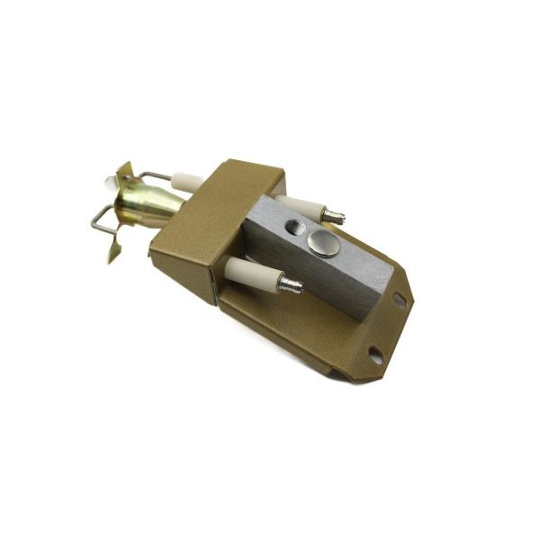
Midco International 6481-90 Ignitor Assembly

Special Price $305.86 Regular Price $339.50
In stock
SKU
6481-90
The Midco International 6481-90 Ignitor Assembly is used to activate the burner ignition in the combustion elements of HVAC systems. It operates by generating a regulated electrical spark or heat source that is dependable in lighting fuel within gas furnaces and boilers. It is designed to fit in the combustion chamber, designed to be interchangeable with compatible burners and attached to the power supply and the control board of the system. Having accurate timing and a constant ability to start the heating cycle, it helps to start the combustion process in residential and light commercial HVAC systems.

https://www.partshnc.com/media/catalog/product/6/4/6481-90.jpg
Manufacturer Name: Midco International
Product Number: 6481-90
OEM Part Number: 6481-90
Product Description: Ignitor Assembly
Weight:0.88lbs/399.16g

Choose the best HVAC equipment parts and supplies from PartsHnC!

  • Same Day Shipping

  • Best Quality And Best Price

  • Wide Range of Inventory

  • Best Customer Service

Have More Questions or Need Help to Place The Order?
Reach us at (866)773-0907 or [email protected]

Write Your Own Review
You're reviewing:Midco International 6481-90 Ignitor Assembly
Your Rating
Customer Questions
What maintenance is required for the Midco International 6481-90 Ignitor Assembly?

Regularly check the ignitor for cracks, buildup, or corrosion. Clean gently with a soft brush and ensure electrical connections are secure. Proper maintenance prevents ignition failures and ensures safe, accurate operation.

What are common issues with the Midco International 6481-90 Ignitor Assembly?

  • Failure to ignite.
  • Cracked or broken ignitor element.
  • Intermittent sparks or misfires.
  • Loose or corroded electrical connections.

Installation Steps

Step 1: Turn off power and gas supply and allow burner to cool completely.

Step 2: Remove burner access panel and disconnect old ignitor wiring carefully.

Step 3: Unscrew and replace with assembly, aligning electrode position correctly.

Step 4: Reconnect wiring per diagram ensuring tight insulated connections.

Step 5: Restore gas and power, test ignition sequence, and verify stable flame.

Step 6: Check for gas leaks and ensure proper flame sensor operation.