Facebook Pixel

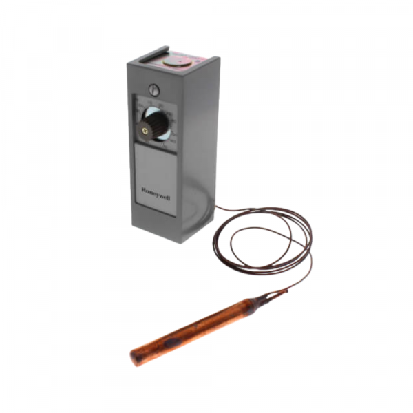
Honeywell T675A1540 Temperature Control W/Bulb Holder 55/175°F 5' Capillary

Special Price $294.05 Regular Price $326.39
In stock
SKU
T675A1540
The Honeywell T675A1540 Temperature controlling parts and its fundamental work is to control the temperature within certain limits in HVAC Systems. It uses a remote bulb sensor which is connected to the control unit through a 5-foot capillary tube. The bulb measures the temperature of the ambient environment and sends the data to the control unit. It then acquaints this information in the control unit whether to power or stop the equipment linked to the specific temperature dials. This model works under a temperature range of 55°F to 175°F and is ideal for use in different industries where temperature is a necessary factor.
https://www.partshnc.com/media/catalog/product/t/6/t675a1540_2.png

Specifications

  • Type: Temperature Control W/Bulb Holder
  • Capillary Length: 5' Temperature: 55°F/175°F
Manufacturer Name: Honeywell
Product Number: T675A1540
OEM Part Number: T675A1540
Product Description: 55/175F,5'Cap,Stat W/Bulb Hldr
Weight:1.25lbs/566.99g

Choose the best HVAC equipment parts and supplies from PartsHnC!

  • Same Day Shipping

  • Best Quality And Best Price

  • Wide Range of Inventory

  • Best Customer Service

Have More Questions or Need Help to Place The Order?
Reach us at (866)773-0907 or [email protected]

Write Your Own Review
You're reviewing:Honeywell T675A1540 Temperature Control W/Bulb Holder 55/175°F 5' Capillary
Your Rating
Customer Questions
What maintenance is required for the Honeywell T675A1540 Temperature Control With Bulb Holder?

This temperature control should be inspected periodically for calibration accuracy and secure bulb placement. Clean the sensing bulb and capillary to prevent debris buildup. Regular checks ensure stable HVAC performance and prevent temperature drift or system inefficiency.

What are common issues with the Honeywell T675A1540 Temperature Control With Bulb Holder?

  • Bulb or capillary damage leading to inaccurate temperature sensing.
  • Drift in temperature calibration causing inconsistent control.
  • Loose mounting or poor bulb placement affecting response.
  • Capillary leaks reducing system responsiveness.

Installation Steps

Step 1: Disconnect power to the equipment and verify the circuit is de-energized before installation.

Step 2: Remove the existing temperature control and note all wiring connections for reference.

Step 3: Mount the control in the designated control panel or enclosure location.

Step 4: Install the sensing bulb in the bulb holder and route the 5-foot capillary tube carefully, avoiding sharp bends or kinks.

Step 5: Connect the wiring to the appropriate terminals according to the equipment wiring diagram.

Step 6: Restore power, adjust the temperature setpoint as needed, and verify proper control operation through a complete heating or cooling cycle.