
Facebook Pixel

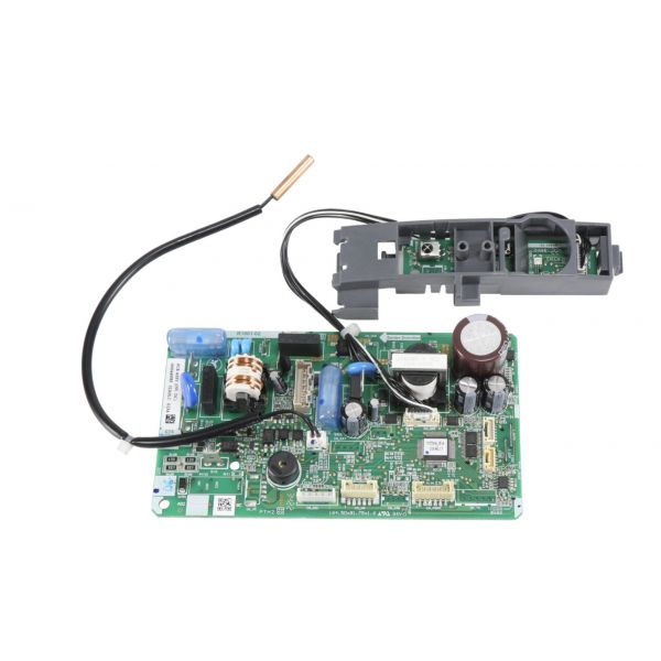
Daikin-McQuay 4026840 Printed Circuit Board Assembly

Special Price $132.70 Regular Price $152.61
In stock
SKU
4026840
The Daikin-McQuay 4026840 Printed Circuit Board Assembly is an electronic part that is used to regulate different operations of HVAC systems. Many electrical components are assembled into this framework to control processes related to temperature, fan speed, and fault detection to superior functionality and durability. They are mainly used in HVAC equipment to improve heat, ventilation, and air conditioning equipment performance. The advantages of the PCB are that it is energy efficient, allows for fine control of temperature, and is more durable than other systems.
https://www.partshnc.com/media/catalog/product/4/0/4026840_Daikin-McQuay_partshnc.jpg

Specifications

  • Type: Printed Circuit Board Assembly
    Manufacturer Name: Daikin-McQuay
    Product Number: 4026840
    OEM Part Number: 4026840
    Product Description: Printed Circuit Board Assembly
    Weight:0.52lbs/235.87g

    Choose the best HVAC equipment parts and supplies from PartsHnC!

    • Same Day Shipping

    • Best Quality And Best Price

    • Wide Range of Inventory

    • Best Customer Service

    Have More Questions or Need Help to Place The Order?
    Reach us at (866)773-0907 or [email protected]

    Write Your Own Review
    You're reviewing:Daikin-McQuay 4026840 Printed Circuit Board Assembly
    Your Rating
    Customer Questions
    What maintenance is required for the Daikin-McQuay 4026840 Printed Circuit Board Assembly?

    Regularly inspect for dust, moisture, or corrosion and clean gently with compressed air. Ensure all wiring and connectors are secure. Proper maintenance prevents malfunctions, ensures accurate system operation, and protects sensitive electronic components.

    What are common issues with the Daikin-McQuay 4026840 Printed Circuit Board Assembly?

    • System failing to power on.
    • Intermittent or failed operations.
    • Burnt or damaged components.
    • Faulty sensor or input/output signals.

    Installation Steps

    Step 1: Turn off power at breaker and verify zero voltage.

    Step 2: Remove access panel and document existing wiring connections carefully.

    Step 3: Disconnect old PCB and remove mounting screws gently.

    Step 4: Install new board aligning standoffs and secure firmly in place.

    Step 5: Reconnect wires per diagram restore power test system operation safely.