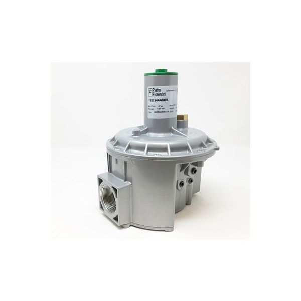
PRODUCT OVERVIEW:
A pressure regulator reduces high incoming gas line pressure to deliver a stable, uniform downstream operating pressure across connected commercial and industrial burners. Fiorentini 31154-5BP OEM is a 1-1/2" balanced valve pressure regulator designed to manage fuel gas flow across commercial piping networks. Operating as part of the Pietro Fiorentini Governor Series, this ANSI Z21.80 / CSA 6.22 certified regulator dampens line surges, maintains tight zero-flow lockup, and ensures dependable fuel delivery across connected equipment.
PRESSURE BALANCE AND INTERNAL SENSING MECHANISM:
The regulator operates using a double diaphragm design with an integral safety membrane to isolate downstream pressure control from incoming line variations. Operating at a maximum inlet pressure of 2 PSIG, internal sensing routes output pressure directly within the valve body to trigger an immediate mechanical response without external impulse lines. Equipped with a black spring set for a 6" to 14" W.C. outlet range (factory set at 8" W.C.), the full lockup mechanism seals tightly against the valve seat when flow stops, protecting downstream piping and components from pressure creep.
LINE INTEGRATION AND FLUID SEATING:
The regulator is equipped with 1-1/2" NPT connection ports, allowing the heavy-duty aluminum body to integrate directly into matching commercial gas supply lines. When downstream demand drops to zero, the internal valve disc forms a bubble-tight seal against the valve seat to stop fluid pass-through entirely. This complete lockup shutoff isolates downstream piping and burner manifolds, preventing pressure accumulation when equipment is idle.
REPLACEMENT GUIDELINES:
Replace the pressure regulator if inspection reveals downstream pressure creep during zero demand, internal seat bypass, a ruptured double diaphragm, or sluggish pressure response. Replacing gas pressure regulators involves working with pressurized fuel gas and safety limiters; work should be performed by a qualified gas technician. The technician must isolate the gas supply, depressurize the line, thread the replacement regulator using gas-rated sealant, perform soap-bubble leak tests, and adjust outlet pressure using downstream test ports. Always verify technical documentation to confirm fitment prior to installation.
COMMON FAILURE SYMPTOMS:
- Downstream pressure creep exceeding set limits during zero-demand lockup conditions.
- Unstable, oscillating, or fluctuating outlet pressure under steady burner load.
- Ruptured internal diaphragm or safety membrane failing to modulate flow.
- Debris accumulation, scoring, or mechanical binding on the internal seating disc.
- Blockage or failure of the integral vent limiter preventing proper diaphragm movement.
EQUIPMENT COMPATIBILITY:
Fiorentini 31154-5BP Balanced Valve Pressure Regulator is intended for select commercial and industrial gas piping networks utilizing Pietro Fiorentini Governor Series regulators. Confirm that your system requires a 1-1/2" connection size, a 2 PSIG maximum inlet rating, internal sensing, and a 6" to 14" W.C. outlet range. Cross-reference original gas train schematics, appliance data plates, and equipment manuals to verify fitment prior to purchasing.
TECHNICAL SPECIFICATIONS:
Product Identification:
Brand: Fiorentini
Part Number: 31154-5BP
Series: Governor Series
Product Type: Balanced Valve Pressure Regulator
Operational & Mechanical Parameters:
Connection Size: 1-1/2 Inch NPT
Sensing Type: Internal Sensing
Shutoff Feature: Full Lockup
Maximum Inlet Pressure: 2 PSIG
Outlet Pressure Range: 6" to 14" W.C. (Factory Set at 8" W.C., Black Spring)
Venting Feature: Integral Vent Limiter (No External Vent Line Required)
Certifications: ANSI Z21.80 / CSA 6.22
 Loyalty Program