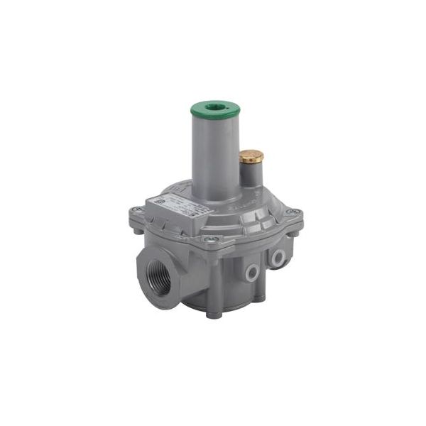
Fiorentini 31153-4BP 1-1/4" Balanced Valve W/7.5" Diaphragm Full Lockup Internal Sensing 1/2" Veny VI CAP
Special Price $448.22 Regular Price $497.53
In stock
SKU
31153-4BP

The Fiorentini 31153-4BP Balanced Valve is a gas pressure regulation component that is used to stabilize and regulate the flow of fuel in supply lines. It has a mechanism that is internal to the diaphragm is a response to changes in pressure and the mechanism moves the valve to a different position to ensure that the outlet pressure of the HVAC units remains balanced. The 1-1/4-inch valve connection is connected to the gas piping and the internal sensing arrangement is used to monitor the conditions of the downstream pressure.
Manufacturer: