Facebook Pixel

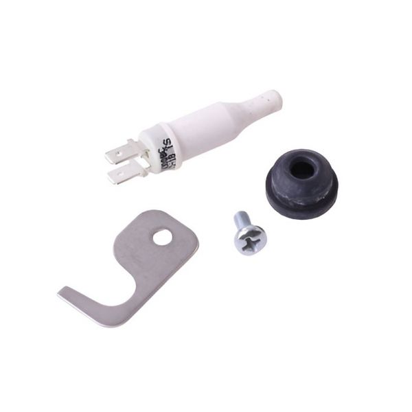
Velocity Boiler Works (Crown) 233081 Flue Sensor Kit BWC070-120-151

Special Price $89.87 Regular Price $103.35
In stock
SKU
233081
The Velocity Boiler Works (Crown) 233081 is a Flue Sensor Kit BWC070-120, a necessary part of natural gas boilers. Constructed of heavy cast iron, it continuously samples the boiler’s exhaust gases to assure safe, efficient operation. It is yet strong enough to cope with high temperatures. The sensor is designed to measure flue gas temperatures and feed the data to the boiler control system to avoid overheating the system and it is essential for the reliability of HVAC systems. It can be used to increase efficiency, decrease emissions, and increase the general safety of the systems, and should be used in all gas boiler installations and maintenance.

https://www.partshnc.com/media/catalog/product/2/3/233081_1.jpg

Specifications

  • Type: Gas Boiler
  • Type of Gas: Natural Gas
  • Material: Cast Iron
  • Weight: 0.06 Lbs
Manufacturer Name: Velocity Boiler Works (Crown)
Product Number: 233081
OEM Part Number: 233081
Product Description: Flue Sensor Kit Bwc070-120 151
Weight:0.06lbs/27.22g

Choose the best HVAC equipment parts and supplies from PartsHnC!

  • Same Day Shipping

  • Best Quality And Best Price

  • Wide Range of Inventory

  • Best Customer Service

Have More Questions or Need Help to Place The Order?
Reach us at (866)773-0907 or [email protected]

Write Your Own Review
You're reviewing:Velocity Boiler Works (Crown) 233081 Flue Sensor Kit BWC070-120-151
Your Rating
Customer Questions
What maintenance is required for the Velocity Boiler Works (Crown) 233081 Flue Sensor Kit?

Regularly inspect the sensor and wiring for dust, debris, or damage. Ensure connections are secure and the sensor is properly positioned in the flue. Avoid exposure to moisture or corrosive substances. Proper maintenance ensures accurate readings and safe boiler operation.

What are common issues with the Velocity Boiler Works (Crown) 233081 Flue Sensor Kit?

  • Incorrect temperature or flue readings.
  • Sensor malfunctions or failure.
  • Loose or corroded wiring connections.
  • Intermittent signal or communication errors.
  • Damage from soot or moisture.

Installation Steps

Step 1: Turn off power to the HVAC system and allow it to cool completely.

Step 2: Locate and remove the existing flue sensor if present.

Step 3: Insert the new flue sensor into the designated flue port securely.

Step 4: Connect the wiring harness to the control board as specified.

Step 5: Ensure proper placement to avoid heat damage or misreading.

Step 6: Restore power and test the system for accurate temperature readings and safe operation.