
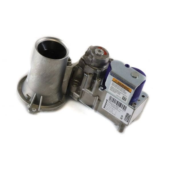
Lochinvar & A.O. Smith 100171985 Gas Valve Assembly
Specifications
- Type: Gas Valve Assembly
Loyalty ProgramProduct Overview:
Provides controlled fuel delivery within hydronic heating equipment. The LOCHINVAR & A.O. SMITH 100171985 Gas Valve Assembly regulates gas admission to the burner system according to the equipment's heating sequence. Its integrated valve and control mechanisms support coordinated fuel delivery, burner ignition, and stable combustion during active heating operation.
Pressure Regulation:
Maintains controlled gas pressure as fuel passes through the valve assembly. Pressure regulation helps provide a consistent gas supply to the burner despite changes within the incoming fuel supply. Stable outlet pressure supports predictable fuel delivery during combustion.
Combustion System Integration:
Forms part of the heating equipment's fuel-control system between the gas supply and burner assembly. Its operation coordinates fuel admission with the equipment's combustion sequence, supporting the transition from fuel demand to burner operation. This integration allows the gas valve to work as part of the overall heating control system.
Replacement Guidelines:
Replacing the Gas Valve Assembly is appropriate if it is damaged, malfunctioning, excessively worn, or otherwise deteriorated. Verify the LOCHINVAR & A.O. SMITH part number 100171985 and the complete heating equipment model number before replacement. Replace the assembly if deterioration affects fuel delivery, valve response, pressure regulation, or normal heating operation.
Common Signs of Wear:
Equipment Compatibility:
The LOCHINVAR & A.O. SMITH 100171985 Gas Valve Assembly is intended for heating equipment that specifies part number 100171985. Verify the complete heating equipment model number and manufacturer's parts documentation before purchasing to help confirm the correct application.
Technical Specifications:
Brand: LOCHINVAR & A.O. SMITH
Part Number: 100171985
Product Type: Gas Valve Assembly
Step 1: Turn off gas supply and electrical power, and check the system is fully shut down and cool.
Step 2: Remove access panel and label all wiring and gas line connections before disassembly.
Step 3: Disconnect wiring harness and carefully unthread gas inlet/outlet connections from the old valve.
Step 4: Install the new gas valve assembly in the same orientation, ensuring correct inlet/outlet alignment.
Step 5: Reconnect wiring and gas fittings securely, using approved thread sealant where required.
Step 6: Restore gas and power, then perform leak test and ignition check to confirm safe combustion and stable flame operation.