
Facebook Pixel

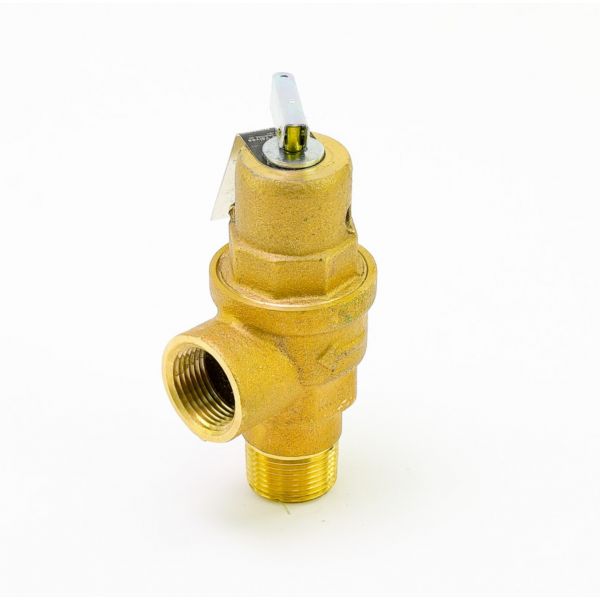
Conbraco Industries 10-624-125 Water Relief Valve 3/4"X3/4" 125 PSI

Special Price $138.87 Regular Price $159.71
In stock
SKU
10-624-125
The Conbraco Industries 10-624-125 Water Relief Valve functions as a vital piece of equipment that specifically serves HVAC systems in water heating applications. The 3/4" x 3/4" valve works at a 125 PSI pressure range to automatically discharge excess pressure while protecting tanks from bursting. The valve protects the system against damage by opening when internal pressure reaches unsafe levels to release water through the discharge mechanism. The device functions primarily as a safety mechanism in residential and commercial water heater systems to ensure reliability. The device prevents overpressure situations which both preserves equipment performance and prolongs HVAC system longevity.
https://www.partshnc.com/media/catalog/product/1/0/10-624-125.jpg

Specifications

  • Type: Water Relief Valve
  • Size: 3/4"MX3/4"F
  • Pressure Range: 125 PSI
Manufacturer Name: Conbraco Industries
Product Number: 10-624-125
OEM Part Number: 10-624-125
Product Description: 3/4"Mx3/4"F 125#Wtrrlf Vlv
Weight:1.13lbs/512.56g

Choose the best HVAC equipment parts and supplies from PartsHnC!

  • Same Day Shipping

  • Best Quality And Best Price

  • Wide Range of Inventory

  • Best Customer Service

Have More Questions or Need Help to Place The Order?
Reach us at (866)773-0907 or [email protected]

Write Your Own Review
You're reviewing:Conbraco Industries 10-624-125 Water Relief Valve 3/4"X3/4" 125 PSI
Your Rating
Customer Questions
What maintenance is required for the Conbraco Industries 10-624-125 Water Relief Valve?

Inspect valve regularly for leaks, corrosion, and mineral buildup. Test the relief mechanism periodically to ensure it opens at rated pressure. Keep discharge outlet clear and replace worn seals or gaskets as needed.

What are common issues with the Conbraco Industries 10-624-125 Water Relief Valve?

  • Valve sticking due to sediment buildup.
  • Leakage from worn seals or seat damage.
  • Incorrect pressure relief or failure to open.
  • Corrosion affecting internal components.
  • Pressure setpoint drift causing premature discharge.
  • Clogging in inlet affecting flow.

Installation Steps

Step 1: Turn off system power and isolate water supply; relieve pressure and allow system to cool.

Step 2: Drain enough water to expose the valve and remove the old relief valve carefully.

Step 3: Clean and inspect the threaded connection or port for debris or damage.

Step 4: Install the new valve using thread sealant, ensuring correct orientation and discharge piping direction.

Step 5: Tighten securely without over-torquing to avoid body damage.

Step 6: Restore water supply and power, then test by briefly lifting the lever to confirm proper discharge.