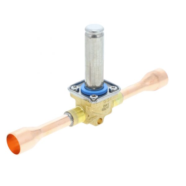
PRODUCT OVERVIEW:
Functioning as a fluid control component within air conditioning, cooling, and refrigeration circuits, the Danfoss 032L7117 N/C 2-Way Solenoid Valve ODF EVR manages internal refrigerant movement across system lines. This inline flow regulation component features a 2-way normally closed architecture paired with 5/8" x 5/8" Outer Diameter Female (ODF) solder connection ports. Resting in a closed state to block fluid movement, the unit opens only when activated, playing a dedicated flow management role within commercial and industrial cooling equipment.
SOLENOID ACTUATION AND VALVE SEATING:
Electrical activation of the solenoid produces a magnetic field within the actuator assembly. The resulting magnetic force moves the internal plunger and transfers movement to the valve seating mechanism. This action changes the seating position to control the valve's internal passage according to the operating signal.
REFRIGERANT FLOW ISOLATION:
Within an operational refrigeration circuit, this component acts as a direct automated line shutoff control to prevent unwanted fluid migration during off-cycles. Positioned along liquid, suction, or hot gas lines, the valve opens during active system operation to permit normal refrigerant circulation and closes during shutdown cycles. By isolating fluid lines when the compressor pauses, the valve prevents liquid refrigerant from draining into the evaporator or migrating into the compressor housing, maintaining proper system pressure differential and protecting downstream mechanical components during non-operational periods.
REPLACEMENT GUIDELINES:
Replacement of the solenoid valve is appropriate when coil failure, internal seat wear, or mechanical binding prevents proper opening or tight shutoff. Electrical failure can prevent the actuator from producing the magnetic force required for valve movement, while worn seating components may allow unwanted refrigerant passage. Replacing a compromised Danfoss 032L7117 restores controlled refrigerant flow and proper valve shutoff.
Common Failure Symptoms:
- Complete loss of refrigerant flow through the valve line during an active operating cycle.
- Continuous refrigerant flow or fluid migration through the valve body when the equipment is turned off.
- Frost, ice, or localized temperature drops forming directly downstream of the valve body due to partial orifice blockage.
- Inability of the cooling equipment to achieve or maintain target storage temperatures.
- Observable cracking, structural deformation, or severe surface degradation around the ODF solder connection ports.
EQUIPMENT COMPATIBILITY:
The Danfoss 032L7117 N/C 2-Way Solenoid Valve 5/8" X5/8" ODF EVR applies to specific refrigeration and air conditioning systems produced by the manufacturer. Before purchasing, verify that the replacement part matches the exact attributes listed in the Technical Specifications table, including the brand, part number, product type, valve type, normal position, connection size, connection type, and series.
Technical Specifications:
Product identification:
Brand: Danfoss
Part Number: 032L7117
Product Type: Solenoid Valve
Series: EVR
Physical specifications:
Connection Size: 5/8" x 5/8"
Valve Type: 2-Way
Valve operation & control:
Normal Position: Normally Closed
 Loyalty Program