
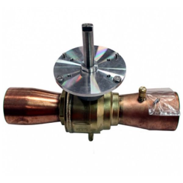
Product Overview:
Provides a dedicated mechanical valve for controlling the passage of refrigerant through connected equipment lines. The Carrier 00PPG000012500 Refrigerant Ball Valve is designed as a ball-type flow-control component with an internal passage that changes according to its operating position. Its construction allows it to control whether the connected pathway is open or closed. The component is used as a physical control point within applicable refrigeration equipment and operates without electronic sensing or signal-processing functions.
Refrigerant Circuit Isolation:
Within the connected circuit, the valve can establish a separation point between adjoining line sections. When a section is isolated, it is no longer placed in direct communication with the adjacent portion through the valve. This system-level role concerns the boundary created between connected areas of the circuit rather than the mechanical process occurring inside the valve.
Replacement Guidelines:
Replacement requires assessing the ball valve configuration, connection arrangement, flow-control requirements, and associated equipment specifications. Carrier 00PPG000012500 Refrigerant Ball Valve should be selected based on the required valve characteristics and operating conditions of the refrigeration system.
Common Failure Symptoms:
- Leakage from the valve body or connected areas.
- Difficulty changing the valve position.
- Restricted movement of the internal mechanism.
- Unintended flow through the controlled line.
- Inability to maintain the selected passage condition.
- Irregular valve operation.
Equipment Compatibility:
The Carrier 00PPG000012500 Refrigerant Ball Valve is intended for applicable refrigeration equipment requiring the corresponding ball valve arrangement. Verify the equipment model number, existing component identification, and manufacturer's parts documentation before purchasing.
Technical Specifications:
Brand: Carrier
Part Number: 00PPG000012500
Product Type: Refrigerant Ball Valve
Installation Steps
Step 1: Turn off HVAC system and safely recover refrigerant before starting.
Step 2: Cut and prepare the refrigerant line where the valve will be installed.
Step 3: Position the valve in the correct flow direction.
Step 4: Braze or connect fittings securely using proper HVAC tools.
Step 5: Allow joints to cool, then pressure-test for leaks.
Step 6: Evacuate system, recharge refrigerant, restore power, and test operation.
Loyalty Program