Facebook Pixel

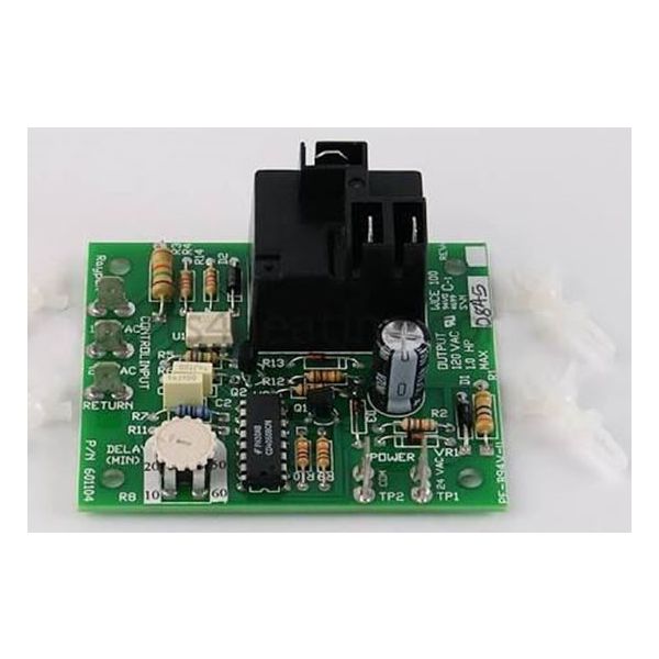
Raypak 005503F Printed Circuit Board Inducer

Special Price $184.08 Regular Price $211.69
In stock
SKU
005503F
The Raypak 005503F Printed Circuit Board Inducer is an authentic PCB that is suitable for use in heating systems in pool heaters and commercial boilers. This particular circuit board controls the inducer fan to provide proper airflow for the combustion chamber and heat exchange. The precise control of the inducer motor improves the performance of the system, raises the energy efficiency, and also increases the equipment’s durability. This PCB is perfect for HVAC systems and technicians as it ensures a constant heating function without frequent breakdowns. Because of its durability, it can last long plays a significant role in maintaining the efficiency of heating systems.
https://www.partshnc.com/media/catalog/product/0/0/005503f_raypak_partshnc.jpg

Specifications

  • Type: Circuit Board
    Manufacturer Name: Raypak
    Product Number: 005503F
    OEM Part Number: 005503F
    Product Description: Pc Board Inducer
    Weight:0.3lbs/136.08g

    Choose the best HVAC equipment parts and supplies from PartsHnC!

    • Same Day Shipping

    • Best Quality And Best Price

    • Wide Range of Inventory

    • Best Customer Service

    Have More Questions or Need Help to Place The Order?
    Reach us at (866)773-0907 or [email protected]

    Write Your Own Review
    You're reviewing:Raypak 005503F Printed Circuit Board Inducer
    Your Rating
    Customer Questions
    What maintenance is required for the Raypak 005503F Printed Circuit Board Inducer?

    Regularly inspect the circuit board for dust, moisture, or corrosion and keep the surrounding area clean and dry. Ensure all electrical connections are secure and free from damage. Avoid exposure to excessive heat or vibration. Always disconnect power before handling to prevent electrical hazards.

    What are common issues with the Raypak 005503F Printed Circuit Board Inducer?

    • Failure to start or control inducer motor.
    • Intermittent or no signal output.
    • Burnt or damaged components on the board.
    • Loose or faulty wiring connections.
    • Error codes or system lockouts.
    • Inconsistent performance during operation.

    Installation Steps

    Step 1: Turn off power and gas supply; apply lockout/tagout verify unit is cool.

    Step 2: Remove access panel and note wiring positions carefully; label connectors.

    Step 3: Disconnect old board inducer carefully from harness connectors; avoid damage.

    Step 4: Mount new PCB inducer securely on bracket; ensure alignment.

    Step 5: Reconnect wires per wiring diagram exactly; confirm polarity.

    Step 6: Restore panel and restore power supply; ensure secure fit.

    Step 7: Test system operation and check for faults; verify no errors.